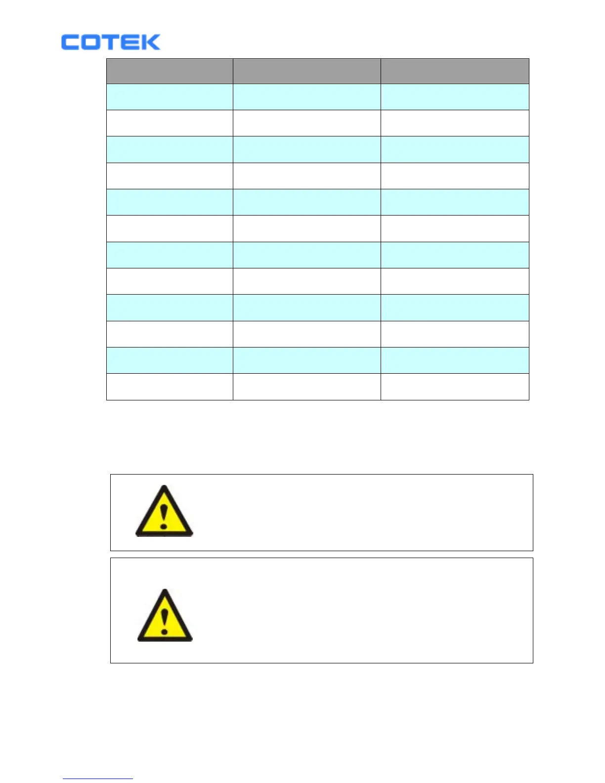
Model No Wire AWG Inline Fuse
ST1000-112 / 212 # 2 150 A
ST1000-124 / 224 # 4 80 A
ST1000-148 / 248 # 6 40 A
ST1500-112 / 212 # 2 200 A
ST1500-124 / 224 # 4 100 A
ST1500-148 / 248 # 6 50 A
ST2000-112 / 212 # 2/0 250 A
ST2000-124 / 224 # 1/0 125 A
ST2000-148 / 248 # 2 70A
ST2500-112 / 212 # 4/0 400 A
ST2500-124 / 224 # 2/0 200 A
ST2500-148 / 248 # 1/0 100 A
3-3-1. Connect the cables to the power input terminals on the front panel of
the inverter. The red terminal is positive (+) and black terminal is
negative (-). Insert the cables into the terminals and tighten screw to
clamp the wires securely.
WARNING!
Make sure all the DC connections are tight (torque
to 9 – 10 ft-lbs, 11.7 – 13 Nm). Loose connections
could result overheat in a potential hazard.
WARNING!
The installation of a fuse must be on positive cable.
Failure to place a fuse on “+” cables running between
the inverter and battery may cause damage to the
inverter and will void warranty.
Also, only use high quality copper wire and keep the cable length short which
is a maximum of 3 - 6 feet.
15