BB
G
A
G
DD
J
G
B
Bond Manufacturing Co., Inc. | Page 6
ASSEMBLY INSTRUCTIONS
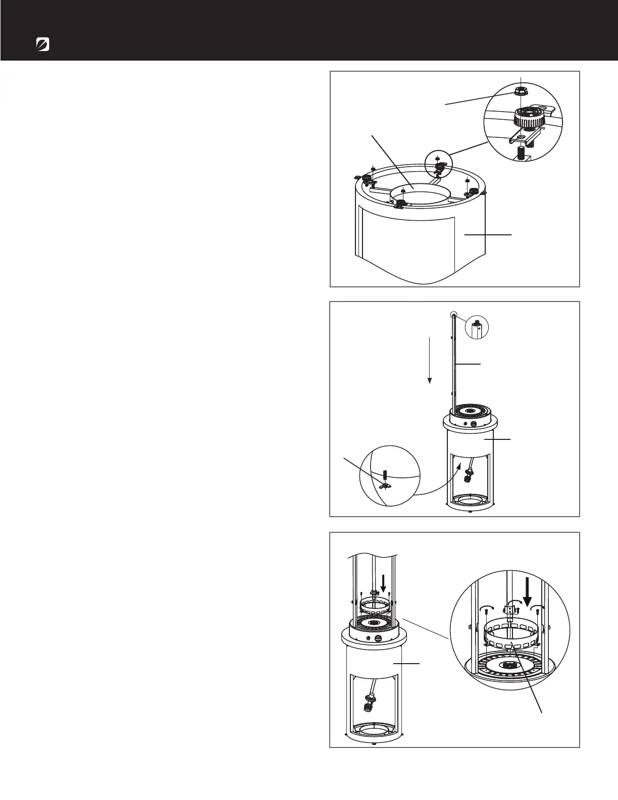
2. Slide the 3 upper supporters (J) into the slots
in the burner at the top of the body (G). Be sure
that they are fully inserted. Tighten the upper
supporters (J) with 3 M5 wing nuts (DD).
Note: Be sure that the hook on the upper
supporter is upwards.
3. Remove the 3 preassembled screws from the
burner at the top of the body (G). Attach the glass
tube ring (B) to the top of the burner using the 3
preassembled screws you just removed.
1. Flip the body (G) upside down on a protected
surface. Remove the glass tube (H).
Attach the tank supporter (A) to the bottom of the
body (G) using 4 M6 nuts (BB). Flip the body (G) over.
Note: Make sure the wing nut on the tank
supporter (A) faces the door on the body (G).
 Loading...