DIRECT VENT GRAVITY GAS WALL HEATER 5
INTRODUCTION
Please read our instructions before you install and use your
furnace. This will help you obtain the full value from this furnace. It
will also help you avoid any needless service costs if the problem
is found within this instruction manual.
Always consult your local heating or plumbing inspector, building
department or electric utility company regarding regulations, codes
or ordinances which apply to the installation of a Direct-Vent Wall
Furnace.
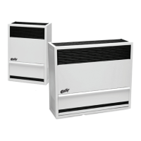
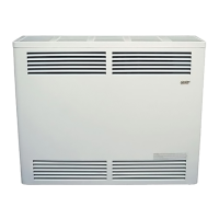
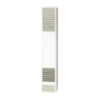
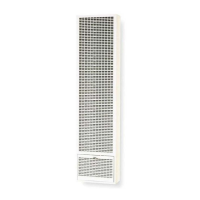
BASIC DESCRIPTION
Your direct-vent wall furnace is shipped ready to install against an
exterior wall up to 9 inches thick. For walls greater than 9 inches,
and up to 24 inches thick, use an optional Vent Extension Kit.
The furnace may burn either Natural or propane gas, depending
on the model you have purchased.
No electric power is required unless furnace is equipped with an
optional blower accessory.
Always consult your local heating or plumbing inspector, building
department or gas utility company regarding regulations, codes or
ordinances which apply to the installation of a direct-vent furnace.
The sealed combustion system draws combustion air directly from
outdoors into the combustion chamber and combustion gases
are discharged directly outdoors through tubes on the rear of the
furnace.
The furnace cabinet is also constructed of heavy-gauge steel and
has a powder paint nish.
The furnace controls are located behind an access door on the
lower front of the furnace. All models are equipped with American
Gas Association and Canadian Gas Association (AGA/CGA) listed
gas valves and pilots.
1) Seal any unused openings in the venting system.
2) Inspect the venting system for proper size and
horizontal pitch, as required in the National Fuel
Gas Code, ANSI Z223.1/NFPA 54 or the Natural Gas
and propane Installation Code, CSA B149.1 and
these instructions. Determine that there is no
blockage or restriction, leakage, corrosion and other
deciencieswhichcouldcauseanunsafecondition.
3) As far as practical, close all building doors and
windowsandalldoorsbetweenthespaceinwhich
the appliance(s) connected to the venting system
are located and other spaces of the building.
4) Closereplacedampers.
5) Turn on clothes dryers and any appliance not
connected to the venting system. Turn on
any exhaust fans, such as range hoods and
bathroom exhausts, so they are operating at
maximum speed. Do not operate a summer
exhaust fan.
WARNING: CARBON MONOXIDE POISONING HAZARD
Failure to follow the steps outlined below for each appliance connected to the venting system being placed
into operation could result in carbon monoxide poisoning or death.
The following steps shall be followed for each appliance connected to the venting system being placed into operation, while all other
appliances connected to the venting system are not in operation:
6) Followthelightinginstructions.Placetheappliance
being inspected into operation. Adjust the thermostat
so appliance is operating continuously.
7) Test for spillage from draft hood equipped appliances
at the draft hood relief opening after 5 minutes
ofmainburneroperation.Usetheameofamatch
or candle.
8) If improper venting is observed during any of the
above tests, the venting system must be corrected
inaccordancewiththeNationalFuelGasCode,
ANSI Z223.1/NFPA 54 and/or natural gas and propane
installation code, CSA B149.1.
9) After it has been determined that each appliance
connected to the venting system properly vents
whentestedasoutlinedabove,returndoors,windows,
exhaustfans,replacedampersandanyother
gas-redburningappliancetotheirprevious
conditions of use.