7
PUSH-PULL LIQUID RECOVERY
The following is recommended to maximize recovery rates;
A. Use shortest length 3/8” (Inside Diameter) Refrigeration Hose on Suction Side of Recovery Unit to Vapor
Port on Tank.
B. Use 3/8” (Inside Diameter) Refrigerant Hoses from system Liquid Service Valve to LIQUID Port on
Recovery Tank.
C. Use an evacuated DOT Tank (90lb or larger, and rated for 550 PSI/38 Bar).
C. If refrigerant is clean, remove all suction side filters, screens, etc.
D. Remove all Schrader type valve cores and any valve depressors from hoses and service valves.
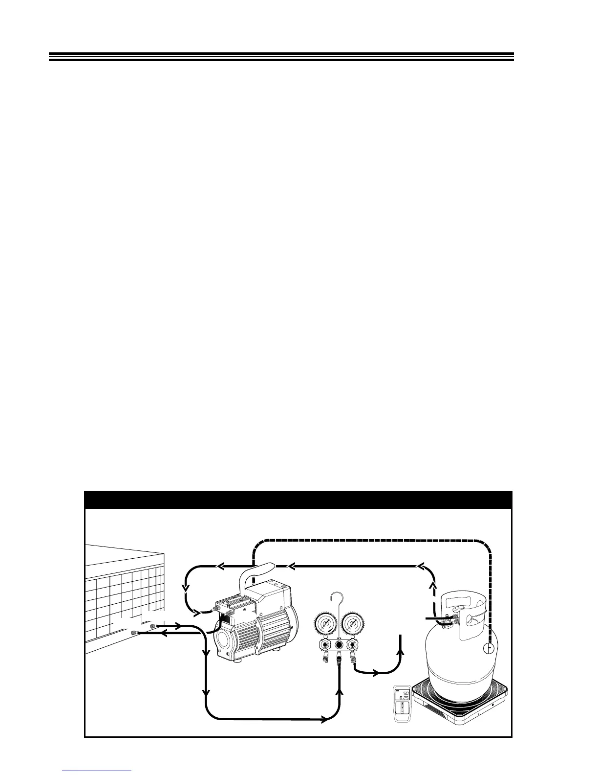
1. Connect the unit as shown in Diagram 3. The technician will need to use a refriger-
ant manifold with sight glass and two spare hoses. The manifold should be con-
nected between the liquid service port of the system being serviced and the DOT
Recovery tank liquid valve. One spare hose should connect from the TR21 IN port to
the DOT recovery tank vapor valve. The other spare hose should connect from the
TR21 OUT port to the vapor service port on the system being serviced.
Note: The DOT recovery tank must be rated for (38 bar) 550 PSI.
2. Close the manifold LO side valve. Open the manifold HI side valve. Open the DOT
recovery tank’s liquid valve.
3. Push the main power switch “ON”.
4. Open the DOT recovery tank vapor valve. A Push-Pull flow is now enabled.
5. Monitor the scale for DOT recovery tank capacity.
6. Monitor the sight glass in the manifold for the presence of liquid refrigerant. Once
liquid refrigerant is no longer being pushed out of the A/C system being recovered,
close the vapor valve on the DOT recovery tank. Let run for 30 seconds, then turn off
unit.
Note: The Push-Pull recovery does not completely recover all the refrigerant. It will be neces-
sary to proceed to Direct Vapor Recovery Operation (page 6) to complete the recovery process.