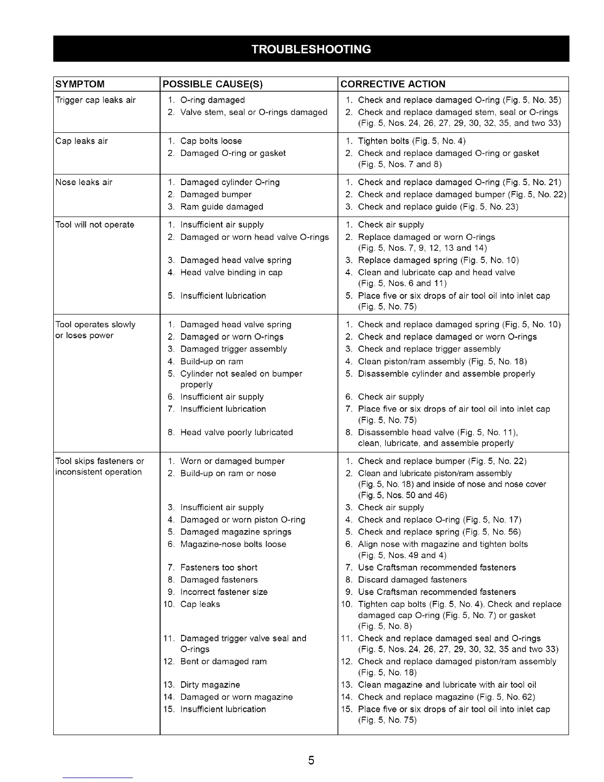
SYMPTOM POSSIBLE CAUSE(S)
Trigger cap leaks air 1. O-ring damaged
2. Valve stem, seal or O-rings damaged
Cap leaks air
Nose leaks air
Tool will not operate
Tool operates slowly
or loses power
Tool skips fasteners or
inconsistent operation
1. Cap bolts loose 1.
2. Damaged O-ring or gasket 2.
1. Damaged cylinder O-ring 1.
2. Damaged bumper 2.
3. Ram guide damaged 3.
1. Insufficient air supply 1.
2. Damaged or worn head valve O-rings 2.
3. Damaged head valve spring
4. Head valve binding in cap
5. insufficient lubrication
1. Damaged head valve spring
2. Damaged or worn O-rings
3. Damaged trigger assembly
4. Build-up on ram
5. Cylinder not sealed on bumper
properly
6. insufficient air supply
7. Insufficient lubrication
8. Head valve poorly lubricated
1. Worn or damaged bumper
2. Build-up on ram or nose
3. insufficient air supply
4. Damaged or worn piston O-ring
5. Damaged magazine springs
6. Magazine-nose bolts loose
7. Fasteners too short
8. Damaged fasteners
9. incorrect fastener size
10. Cap leaks
11.
12.
13.
14.
15.
Damaged trigger valve seal and
O-rings
Bent or damaged ram
Dirty magazine
Damaged or worn magazine
insufficient lubrication
CORRECTIVE ACTION
1. Check and replace damaged O-ring (Fig. 5, No. 35)
2. Check and replace damaged stem, seal or O-rings
(Fig. 5, Nos. 24, 26, 27, 29, 30, 32, 35, and two 33)
Tighten bolts (Fig. 5, No. 4)
Check and replace damaged O-ring or gasket
(Fig. 5, Nos. 7 and 8)
Check and replace damaged O-ring (Fig. 5, No. 21)
Check and replace damaged bumper (Fig. 5, No. 22)
Check and replace guide (Fig. 5, No. 23)
Check air supply
Replace damaged or worn O-rings
(Fig. 5, Nos. 7, 9, 12, 13 and 14)
3. Replace damaged spring (Fig. 5, No. 10)
4. Clean and lubricate cap and head valve
(Fig. 5, Nos. 6 and 11 )
5. Place five or six drops of air tool oil into inlet cap
(Fig. 5, No. 75)
1. Check and replace damaged spring (Fig. 5, No. 10)
2. Check and replace damaged or worn O-rings
3. Check and replace trigger assembly
4. Clean piston/ram assembly (Fig. 5, No. 18)
5. Disassemble cylinder and assemble properly
6. Check air supply
7. Place five or six drops of air tool oil into inlet cap
(Fig. 5, No. 75)
8. Disassemble head valve (Fig. 5, No. 11),
clean, lubricate, and assemble properly
1. Check and replace bumper (Fig. 5, No. 22)
2. Clean and lubricate pistonlram assembly
(Fig. 5, No. 18) and inside of nose and nose cover
(Fig. 5, Nos. 50 and 46)
3. Check air supply
4. Check and replace O-ring (Fig. 5, No. 17)
5. Check and replace spring (Fig. 5, No. 56)
6. Align nose with magazine and tighten bolts
(Fig. 5, Nos. 49 and 4)
7. Use Craftsman recommended fasteners
8. Discard damaged fasteners
9. Use Craftsman recommended fasteners
10. Tighten cap bolts (Fig. 5, No. 4). Check and replace
damaged cap O-ring (Fig. 5, No. 7) or gasket
(Fig. 5, No. 8)
11. Check and replace damaged seal and O-rings
(Fig. 5, Nos. 24, 26, 27, 29, 30, 32, 35 and two 33)
12. Check and replace damaged piston/ram assembly
(Fig. 5, No. 18)
13. Clean magazine and lubricate with air tool oil
14. Check and replace magazine (Fig. 5, No. 62)
15. Place five or six drops of air tool oil into inlet cap
(Fig. 5, No. 75)
 Loading...