Do you have a question about the Craftsman 82312 and is the answer not in the manual?
Key safety rules for operating the meter safely, including voltage limits and mode usage.
Warnings about high voltage, improper connections, and equipment protection.
Explains symbols indicating general hazards, warnings, and cautions.
Explains symbols for maximum voltage, hazardous terminals, and double insulation.
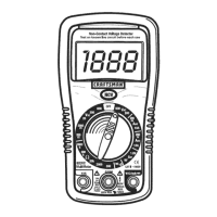
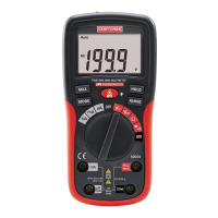
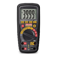
Describes the NCV sensor, indicator light, LCD display, and NCV button.
Details the 10A, COM, and general function jacks for test leads.
Describes the meter's protective rubber holster.
Symbols for continuity, diode, AC, and DC measurements.
Symbols for units like Volts, Amps, Ohms, and prefixes like milli and kilo.
Technical details for the AC voltage detection feature.
Specifications for measuring DC voltage across various ranges.
Specifications for measuring AC voltage across various ranges.
Specifications for measuring DC current across various ranges.
Specifications for measuring AC current across various ranges.
Specifications for measuring resistance across various ranges.
Details on accuracy, measurement ranges, and conditions for various functions.
Information on display, polarity, measurement rate, battery, fuses, and operating conditions.
Notes on weight, size, and product approvals.
Details the meter's intended use and insulation classifications.
Clarifies the meaning of UL listing regarding accuracy.
Explains different overvoltage categories (I, II, III, IV).
First step in battery installation: disconnect leads from meter.
Procedure for removing the rear battery cover.
How to insert the battery, observing correct polarity.
Reattaching and securing the battery compartment cover.
Safety warning about operating the meter before cover is fastened.
Suggestion to check fuses and batteries if meter is not working.
Emphasizes the danger of high-voltage circuits and need for care.
Explains random readings when test leads are not connected to a device.
Explains how the NCV feature detects AC voltage near a source.
Crucial safety warning to test the NCV detector on a known live circuit.
Advises checking battery strength before using NCV mode.
Step-by-step guide on how to use the NCV function.
Warns about probe tip length limitations in recessed outlets.
Caution against measuring AC voltage when motors are switched on/off.
Instructions to set the dial to the 600 VAC position.
How to connect the black and red test leads to the COM and V jacks.
How to touch the probe tips to the neutral and hot sides of the circuit.
How to read the measured AC voltage from the display.
Caution against measuring DC voltage when motors are switched on/off.
Instructions to set the dial to the highest VDC position.
How to connect the black and red test leads to the COM and V jacks.
How to touch the probe tips to the negative and positive sides of the circuit.
How to read the measured DC voltage and adjust for resolution.
Important safety note to remove batteries from devices before testing.
Instructions to select the 1.5V or 9V BAT position.
How to connect the black and red test leads to the COM and V jacks.
How to touch the probe tips to the negative and positive sides of the battery.
How to read the measured battery voltage.
Warning about the 30-second limit for 10A measurements.
How to set up the meter for 200mA AC/DC current.
How to set up the meter for 10A AC/DC current.
Steps to open the circuit and remove power before measurement.
How to connect the probes in series with the circuit.
Apply power and read the current measurement from the display.
Safety warning before taking resistance measurements.
Instructions to set the dial to the highest Ω position.
How to connect the black and red test leads to the COM and Ω jacks.
How to touch the probes across the component or circuit.
How to read resistance and adjust for higher resolution.
Safety warning: do not check continuity on live circuits.
Instructions to set the dial to the continuity (⚫))) position.
How to connect the black and red test leads to the COM and Ω jacks.
How to touch the probes to the circuit or wire.
How the audible signal and display indicate continuity.
Instructions to set the dial to the diode (→⚫))) position.
How to connect the black and red test leads to the COM and Ω jacks.
How to touch the test probes to the diode terminals.
Expected readings for good, shorted, and open diodes.
Safety warning before accessing battery or fuse covers.
Safety warning about operating meter with covers unsecured.
Tips on keeping the meter dry, storing it, and handling it gently.
How to clean the meter case, avoiding chemicals.
Using fresh batteries and removing them for long-term storage.
Explains the icon indicating low battery voltage.
Steps to disconnect leads, remove holster, and access the battery compartment.
Procedures for replacing the battery and reassembling the meter.
Safety warning before accessing battery or fuse covers.
Steps to disconnect leads, remove holster, and access the fuse compartment.
Procedures for replacing fuses and reassembling the meter.
Common issues and solutions when the meter fails to operate.
Resources for understanding meter operation or seeking help.
Lists common replacement parts with item numbers.
Contact information for ordering replacement parts.
| Model | 82312 |
|---|---|
| Brand | Craftsman |
| Continuity Test | Yes |
| Diode Test | Yes |
| Battery Type | 9V |
| Auto Power Off | Yes |
| Low Battery Indicator | Yes |
| Category | Multimeter |
| Display Type | LCD |
| Functions | Voltage, Current, Resistance, Continuity, Diode Test |