EasyManua.ls Logo

Craftsman 919.176730 - User Manual

Craftsman 919.176730
18 pages
Print Icon
To Next Page IconTo Next Page
Loading...
S_FA/RS
OWNERS
MANUAL
MODEL NO.
919.17673g
919.17683
aMPORTANT:
Read the Safety Guidelines
and AH instructions
Carefully Before Operating
CRAFTSMAN AiR COMPRESSOR
ASSEMBLY
OPERATION
MAINTENANCE
REPAIR PARTS
Record in the spaces provided.
(1) The model number which can be
found on the tabel on the rear of the
air tank.
(2) The code number which can be
found on the foil tabel on the rear of
the air tank.
(3) The Manufacturers Number
(MFG.,.) {ASME Code Compres-
sors onty) is located on the metst
date plate which is welded onto the
backside of the air tank. (This data
plate is painted the same cotor as the
tank.)
(4) The Motor Manufacturers name
which is mocated on the motor tabel
or specification plate.
(5) The Motor Mfg. number- atso
_ocsted on the motor _abel or specifF
cation plate,
Retain these numbers for future
reference.
Model No
Code No .............................................................
Mfg. No,
Motor Mfg. Name
Motor Mfg. No
Sears, Roebuck and Coo, Chicago, IL 60684 U.S.A.
SI-30-14-4-D 6/89
Question and Answer IconNeed help?

Do you have a question about the Craftsman 919.176730 and is the answer not in the manual?

Summary

Safety Guidelines

Specification Chart

Glossary

Accessories for Use with Sears Air Compressors

General Information

Description of Operation

Assembly Instructions

Items You Will Need To Assemble Your Compressor

Lists tools and materials required for compressor assembly.

Installing Handle

Step-by-step guide for attaching the unit's handle.

Installing Tank Pressure Gauge

Instructions for installing the tank pressure gauge.

Installing Regulator

Guide for attaching the pressure regulator to the manifold.

Installation and Break-in Procedures

Location of the Air Compressor

Guidance on selecting a suitable operating location for the compressor.

Extension Cords

Recommendations for using extension cords with the air compressor.

Lubrication and Oil

Instructions for adding and checking the compressor oil.

Grounding Instructions

Operating Procedures

Break-in Procedures

Essential steps to prepare the compressor before initial use.

Maintenance

Air Compressor

General advice on keeping the air compressor clean and ventilated.

Air Filter - Inspection and Replacement

Procedure for checking and replacing the air filter.

Oil - Checking and Changing

Guidance on monitoring and performing oil changes for the compressor.

Check Valve - Replacement

Steps for removing and replacing the check valve.

Safety Valve - Inspection

How to inspect the safety valve for proper operation.

Motor

Information on the motor's thermal overload protector and reset button.

Belt - Replacement

Instructions for replacing the drive belt on the compressor.

Pulley and Flywheel - Alignment

How to align pulleys and flywheel for proper belt operation.

Storage

Troubleshooting Guide

Air Compressor Diagram

Compressor Pump Diagram

Parts List

Service

How to Order Repair Parts

Overview

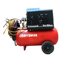
This document is the owner's manual for a Sears Craftsman Air Compressor, specifically models 919.176730 and 919.176830. It provides comprehensive information on assembly, operation, maintenance, and repair parts.

Function Description:

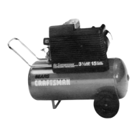
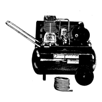
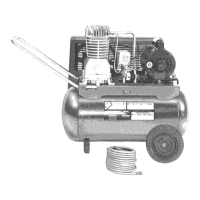
The Sears Craftsman Air Compressor is a 2-cylinder, single-stage air compressor unit designed to compress air. It consists of an air compressor pump, an air tank, air hose, wheels, a handle, an air chuck, and associated controls. The compressed air can be used for various applications, including operating paint spray guns, air tools (sanders, drills, impact wrenches, hammers), caulking guns, grease guns, airbrushes, sandblasters, power washers, inflating tires and plastic toys, and spraying weed killers or insecticides.

The compressor operates by pistons moving up and down in the cylinders. On the downstroke, air is drawn in through the air intake filter and then through the intake valves. On the upstroke, air is compressed and forced out through the exhaust valve, through the outlet tube, through the check valve, and into the air tank. Working air becomes available once the tank pressure exceeds the required pressure at the air outlet.

Key components for operation include:

  • Pressure Switch: Automatically starts the motor when tank pressure drops below the "cut-in" pressure and stops it when the "cut-out" pressure is reached.
  • Regulator: Controls the air pressure coming from the air tank to the outlet. It can be adjusted clockwise to increase pressure and counterclockwise to decrease pressure.
  • Tank Pressure Gauge: Indicates the reserve air pressure in the tank.
  • Outlet Pressure Gauge: Shows the air pressure available at the outlet side of the regulator, which is always less than or equal to the tank pressure.
  • Check Valve: Allows compressed air into the tank when operating and closes to keep air in the tank when "cut-out" pressure is reached.
  • Pressure Release Valve: Located on the pressure switch, it automatically releases compressed air from the compressor head and outlet tube when the compressor reaches "cut-out" pressure or is shut off, allowing the motor to restart freely.
  • Safety Valve: A crucial safety feature that "pops out" at a factory-set pressure (slightly higher than the pressure switch cut-out setting) if the pressure switch fails to shut off the compressor, preventing over-pressurization and potential rupture or explosion of the air tank.

Important Technical Specifications:

Specification Model 919.176730 Model 919.176830
Horsepower 3 3
Displacement CFM 11.3 11.3
Bore 2 7/8" 2 7/8"
Stroke 2" 2"
Voltage-Single Phase 120/240V 120/240V
Min. Branch Circuit Req. 15 amp 15 amp
Fuse Type Fusetron Type "T" Fusetron Type "T"
Air Tank Capacity 20 Gallons 20 ASME
Approx. Cut-in Pressure 80 80
Approx. Cut-out Pressure 100 100
SCFM @ 40 psig 8.8 8.8
SCFM @ 90 psig 7.7 7.7
SCFM @ 100 psig 7.3 7.3
U.L. Listed Yes Yes

Both models feature dual voltage motors (120V and 240V) and are factory-wired for 120V operation, with instructions provided for conversion to 240V. A 15 amp circuit breaker or Fusetron Type "T" time delay fuse is preferred for circuit protection. If an extension cord is used, it must be a 3-wire, 3-blade grounding type, no longer than 50 feet, and with a minimum wire size of 12 gauge (AWG).

Usage Features:

  • Assembly: Requires installing the handle, rubber foot strip, wheels, tank pressure gauges, and regulator. Pipe thread sealant is necessary for gauge and regulator installation.
  • Location: The compressor should be operated in a clean, dry, and well-ventilated area, at least 12 inches away from walls or obstructions to ensure proper cooling. The air filter must be kept clear.
  • Break-in Procedure (One-time): Before first use, the compressor must run for 30 minutes with the regulator fully open to prevent tank pressure build-up. After 30 minutes, the regulator is closed until the tank reaches cut-out pressure and the motor stops.
  • Operation: Before attaching accessories, the pressure switch lever must be in the "OFF" position, and the regulator outlet closed. After attaching, move the pressure switch to "ON/AUTO" and allow tank pressure to build. Adjust the regulator to the desired pressure for the accessory.
  • Shutdown: Set the pressure switch to "OFF", turn the regulator counter-clockwise to zero outlet pressure, remove accessories, slowly bleed air from the tank until approximately 20 psi, and drain water from the air tank.
  • Safety: Emphasizes the importance of grounding, proper ventilation when spraying flammable materials, wearing safety goggles, and never pointing nozzles at people. It warns against touching hot parts, operating without the belt guard, and modifying the air tank.

Maintenance Features:

  • General Cleaning: Keep the air compressor clean, blowing off dust and dirt from fins and other parts to ensure proper cooling.
  • Air Filter: Inspect and replace the air filter regularly to maintain full capacity. Never operate the compressor without the air filter.
  • Oil: Compressors are shipped without oil. It is crucial to add 16 fluid ounces of Sears 9-16426 or SAE 20-20W SF motor oil (or SAE 10W for winter) to the crankcase before first operation. Check oil level daily, ensuring it's even with the top of the fill hole. Change oil every 100 hours of operation. Overfilling can cause premature failure.
  • Check Valve: Can be cleaned with solvent or replaced if defective.
  • Safety Valve: Periodically pull the ring to ensure it operates freely. A stuck or malfunctioning safety valve must be replaced with one of the same pressure rating.
  • Motor: Equipped with a manual thermal overload protector that shuts off the motor if it overheats. To restart, allow the motor to cool, turn the unit off, depress the red reset button, and turn the unit on.
  • Belt: Replacement involves unplugging the compressor, removing the front belt guard, loosening the motor hold-down plate to tilt the motor, removing the old belt, and installing a new one, ensuring it's centered on the grooves. Tension is adjusted by tightening the wing nut.
  • Pulley and Flywheel Alignment: The compressor flywheel and motor pulley grooves must be aligned within 1/32" to ensure proper belt operation.
  • Storage: Before storing, perform necessary maintenance, drain water from the air tank, set the switch to "OFF", unplug the unit, remove accessories, protect the electrical cord and air hose, and store in a clean, dry location.

The manual also includes a detailed troubleshooting guide for common issues like excessive tank pressure, air leaks, knocking noise, insufficient air supply, excessive belt wear, squealing, and motor not running. It provides a parts list and diagrams for both the overall air compressor and the compressor pump, facilitating identification and ordering of repair parts. Sears, Roebuck and Co. offers a one-year warranty for residential use and a ninety-day warranty for commercial/rental use.

Craftsman 919.176730 Specifications

General IconGeneral
BrandCraftsman
Model919.176730
CategoryAir Compressor
LanguageEnglish

Related product manuals