Do you have a question about the Craftsman 921.166370 and is the answer not in the manual?
Ensures guards are attached, power cord is free of moving parts, twisting/crimping.
Surfaces can cause burns; allow unit to cool before maintenance.
Operate on stable position; avoid elevated/tipped positions.
Wear safety glasses; drain tank before maintenance; never point nozzle at people.
Use in confined areas; keep children/pets away; does not provide breathable air.
Avoid rain/wet conditions; use authorized personnel for repairs; ensure proper grounding.
Avoid combustible materials/vapors; locate away from spray area; avoid indoors.
Drain tank daily; replace if leaking; do not modify settings.
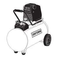
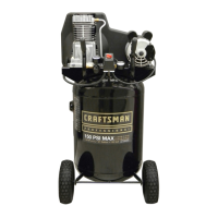
Indicates outgoing air pressure to the tool, controlled by regulator.
Closes when pump is not operating to retain tank pressure.
Indicates the reserve air pressure in the tank.
Offers a quick release feature for attaching and removing the air hose.
Allows excess tank pressure to escape when above maximum rated pressure.
Controls motor power and cut-in/cut-out pressure settings.
Automatically releases compressed air when cut-out pressure is reached.
Controls air pressure from the tank; adjust by turning knob.
Used to drain condensation from the air tank.
Provides clean air to the pump; keep free of debris.
Indicates the oil level in the crankcase.
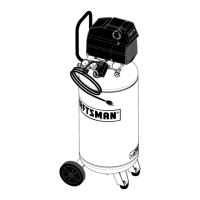
Locate in clean, dry, ventilated area with 12 inches space; ensure filter intake is clear.
Product must be grounded for shock risk reduction; use proper plug and outlet.
Use 3-wire, grounding extension cords; ensure condition and gauge are adequate.
No break-in procedure required; product is factory tested for performance.
Steps for safe and proper daily operation, including checks and connections.
Steps for safe shutdown, including draining the tank and unplugging.
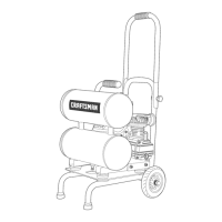
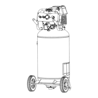
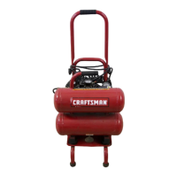
Steps to safely detach the compressor from its dolly.
Steps to safely secure the compressor onto its dolly.
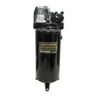
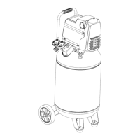
| Brand | Craftsman |
|---|---|
| Model | 921.166370 |
| Category | Air Compressor |
| Language | English |