FIG. 1
FIG. 1A
Locking Short
Leg Connector
Locking Long
Leg Connector
Long Leg
Short Leg
4
5
7
6
90° Locking
Elbow Connector
90° Locking
Elbow Connector
1
1
1 1
90°
Locking
Elbow
Frame
Rail
1
2
5
4
2
2
2
2
FIG. 1B
4
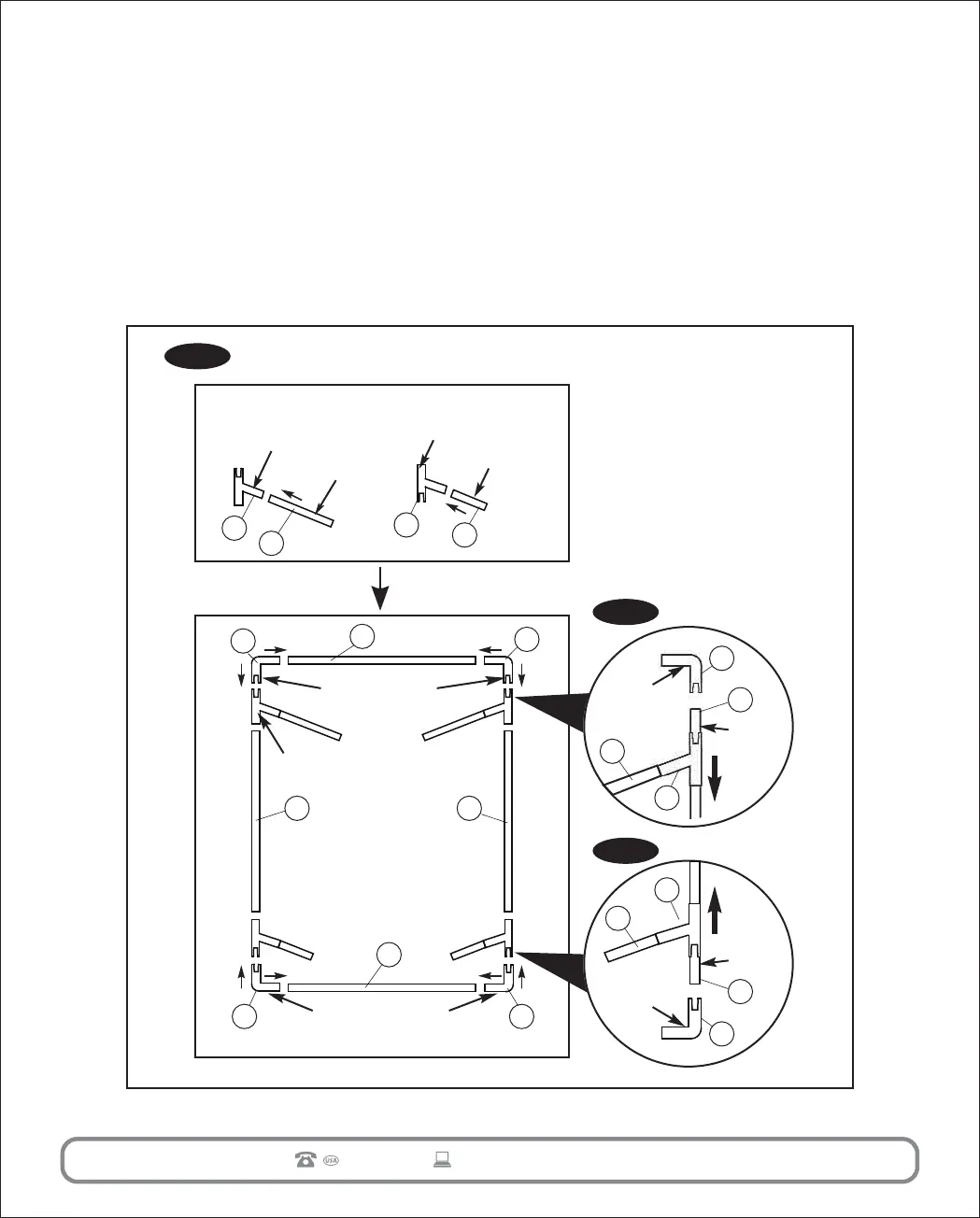
1. Frame Assembly
A. Lay out the components as shown in FIG. 1. Follow the instructions under
ASSEMBLING THE TARGET below.
B. Lay out the Frame components as shown in FIG. 1. Slide the Locking Leg
Connectors onto the Side Rails as shown in FIG. 1A&1B allowing enough
room to connect the 90° Locking Elbow Connectors. Continue to connect
the balance of the components. Press all connectors together firmly.
1-877-472-4296
AFTER SALES SUPPORT
6510
gsskatina@gmail.com
Frame
Rail
90°
Locking
Elbow
1
2
6
7