* Lay out WQ02a, WQ05b and WQ05a as shown.
* Attach WD09 between WD07 and WD04 with wood
1
Note: It is vital that the fort
be level after this
phase!
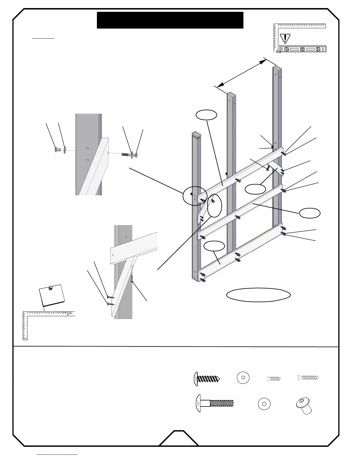
STEP :
TOWER ASSEMBLY
WQ06a
e3
(3)
d1
(3)
b2
k2
a3
a1
(9)
(12)
(4)
HARDWARE NEEDED
(3)
k1
WD07
WC13
e3
d1
b2
k2
k2
d
k1
WD09
WQ02a
WQ05b
WQ05a
ITEMS NEEDED
a3
k2
b2
(2)
k1
d1
k2
e3
WF04
(2) WC13 Platform Support 1×3×15 5/16
(1) WQ05b Upright-D 3×4×89 5/16
(1) WQ05a Upright-C 3×4×89 5/16
(1) WQ02a Upright-A 3×4×78 3/4
(1) WD07 Floor Joist 5/4×4×52 13/16
(1) WF04 Sandbox Board-B 1×6×52 13/16
(1) WD09 First Floor Guardrail 1× 4×52 13/16
* Insert all nut barrels "d1" into the uprights respectfully.
* Attach WD07 into the pre-drilled holes with bolt "e3".
Right wall of tower
* Attach both WC13 as shown.
* Attach WD04 into the pre-drilled holes with wood screws "b2".
N
o
t
e
!
I
m
p
o
r
t
a
n
t
MAKE SURE FRAME IS
SQUARE BEFORE
PROCEEDING TO
NEXT PHASE!
N
o
t
e
!
I
m
p
o
r
t
a
n
t
a1
a3
a3
a1
screws "b2".
17
30 7/8"