p.8
Features Overview
3
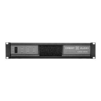
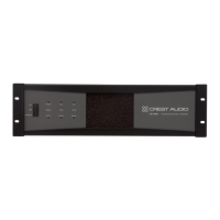
Front Panel
1
Rack Mounting Ears
Two holes (four on 4U amplifiers) are provided on each front mount-
ing ear..
2
3-Position Power Switch
With this switch in the “up” position the amplifier is On.The middle
position is Off and the lower position is marked Remote. When
switched to Remote,the amplifier must be activated by the sequential
turn on/turn off (STO) circuit.
3
Protect LED
If the amplifier enters any of its Protect modes, the output relay will
open,and this LED will light.
4
Active LED
The Active LED indicates the amplifier is turned on and the output
relays have closed.
5
ACL LEDs
Each channel has an ACL (Active Clip Limiting) LED.If a channel reach-
es the clipping point,this LED will light to show that the ACL circuit is
active.
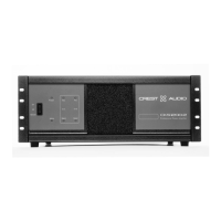
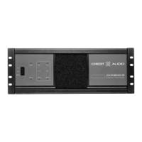
Front Panel - CKi 800s shown
1 2 3 4
7
5
6
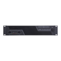
This chapter identifies the switches,indicators,connectors and functional com-
ponents of all CKi amplifiers.Keep in mind that this chapter is only as an
overview of the amplifier’s layout,and does not contain all the information nec-
essary to effectively operate the CKi. For more detailed information on the
items listed here,be sure to read this entire manual.