p.11
Features Overview
3
Rear Panel cont.
6
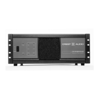
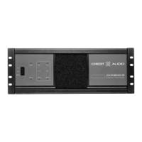
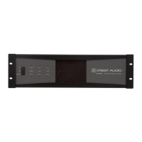
Output Connectors
A barrier strip provides output connection terminals for two speak-
ers operating in stereo or parallel, for a single speaker wired in a
bridged mono configuration,or for constant voltage distribution.Bare
wire or spade lugs may be used to make barrier strip connections.
7
Ground Lift Switch
This switch disconnects the audio ground from the chassis ground in
the amplifier.
8
Module Bay
All CKi amplifiers possess a module bay configured to accept inter-
changeable plug-in modules.Your amplifier may have been factory
configured with a module. Information on all CKi modules is available
in this manual.
See – Chapter 7 NexSys Modules for more information.
9
Mode Select Switch
This switch reconfigures the amplifiers outputs for stereo,parallel,or
bridged operation..
0
Input Attenuators
Each channel has an attenuator knob to adjust the channel’s output
from -∞ to maximum power.
¡
Status LEDs
The “Protect,” “Signal,” and “ACL” LED’s on the rear panel serve the
same function as the front panel LED’s of the same names.The “IGM”
LED will light if the amplifier’s IGM protection circuit engages.
Input Connectors
The CKi uses one 3-pin Phoenix connector per channel for balanced
line-level audio input.These inputs can also be setup to accept an
unbalanced signal.
Gain (input sensitivity) Select Switch
This switch sets the amplifier’s gain structure as constant sensitivity
(0dB setting) or constant gain (x20 or x40 settings).
Do not adjust the
mode selection switch
while the amplifier is
turned-on.
a
In situations where an
UNBALANCED sig-
nal is fed to the amp,
it’s important to ground
the unused input.If the
inverting (-) input of an
amp channel is left float-
ing,the gain will drop
by 3 dB.
+
12
13