CNX Enhanced Ethernet Expansion Card Crestron CNXENET+
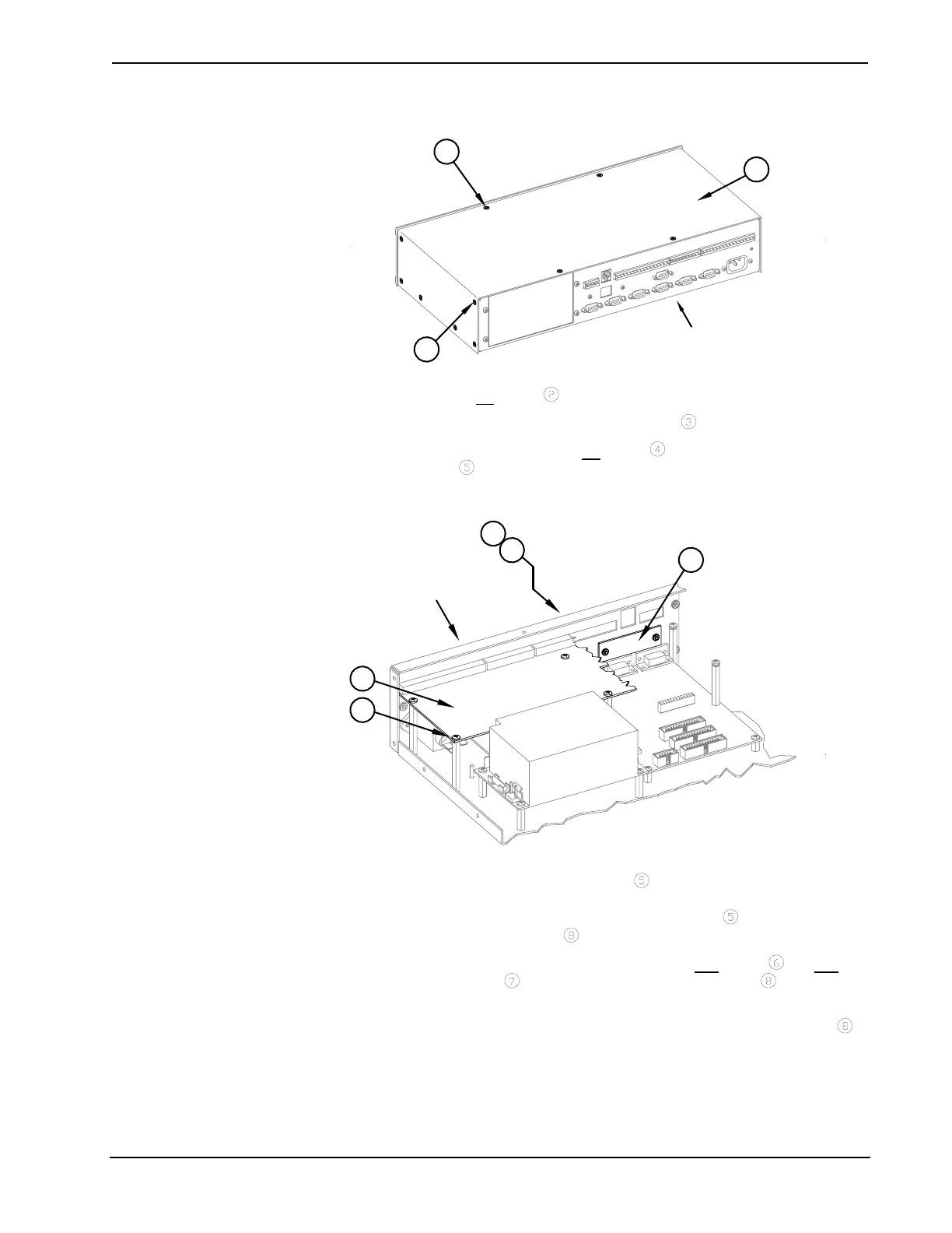
CNMSX Installation (1 of 3)
3
1
2
REAR PANEL
(REFERENCE ONLY)
2. Remove six
screws from each side of the control system.
3. Lift and remove control system top cover
.
4. As shown below, remove six
screws that secure I/O printed circuit
board
to the control system.
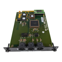
CNMSX Installation (2 of 3)
8
7
4
5
6
REAR PANEL
(REFERENCE ONLY)
5. Slide the I/O printed circuit board
toward the front panel of the
control system so that the rear connectors are clear of the rear panel
slots and reposition the I/O printed circuit board
to gain access to the
LAN/DPA cover plate
.
6. Using a #1 Phillips tip screwdriver, remove two
screws and two
lock washers
that secure the LAN/DPA cover plate to the control
system rear panel.
7. From inside the control system, remove the LAN/DPA cover plate
.
8. For older model control systems, carefully push the computer interface
ribbon cable aside to make room for the CNXENET+. For newer
systems, make sure that cable does not interfere with CNXENET+
placement.
4 • CNX Enhanced Ethernet Expansion Card: CNXENET+ Operations & Installation Guide – DOC. 8153A