DIN-TSTAT-FCU
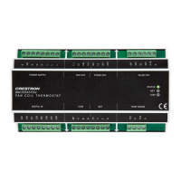
DIN-Rail Heating and Cooling Fan-Coil Thermostat
Installation Guide
Description
The Crestron
®
DIN-TSTAT-FCU is a DIN-rail mounted fan-coil unit (FCU) controller
designed for use in two-pipe applications. It may be operated as a stand-alone controller
or integrated with a home automation system or building management system (BMS). The
DIN-TSTAT-FCU is designed to control various heating and cooling congurations.
Additional Resources
Visit the product page on the Crestron website (www.crestron.com)
for additional information and the latest rmware updates. Use a QR
reader application on your mobile device to scan the QR image.
Installation
Use the DIN-TSTAT-FCU in a well-ventilated area. The venting holes should not be
obstructed under any circumstances. The DIN-TSTAT-FCU mounts to a DIN rail. Refer to
the following diagram when installing.
To install the DIN-TSTAT-FCU, press it onto the DIN rail until it snaps into place.
DIN-TSTAT-FCU
DIN rail
DIN rail release
To remove the DIN-TSTAT-FCU from the DIN rail, use a small, at object (such as a
at-head screwdriver) to pull the DIN rail release tabs, and then tilt the bottom of the
DIN-TSTAT-FCU away from the DIN rail.
NOTE: Certain third-party DIN cabinets provide space for an informational label
between each DIN rail row. Crestron’s Engraver software (version 4.0 or later) can
generate appropriate labels for all Crestron DIN rail products.
Fan Coil Types
The DIN-TSTAT-FCU is a universal FCU controller designed for use in 2-pipe applications.
The DIN-TSTAT-FCU can control a variety of valve types:
• Modulated 0-10 Vac Valve
• Modulated OP-CL 24 Vac Valve
• Spring Loaded 24 Vac Valve
• Modulated OP-CL 230 Vac Valve
• Spring Loaded 230 Vac Valve
• 1-2 Stage Direct-expansion System
NOTE: All set points values for valve, fan speed, and temperature are dened by setting
various parameters according to the customer's needs.
NOTE: For details on controlling the fan speed, refer to the "Fan Speed Control"
section.
Modulated 0-10 Vac
This device is designed for use with a 2-pipe, 3-speed FCU with a 0-10 Vac modulated
valve.
In this case, the valve performs regulation in the ∆T vicinity of set point. The valve opens
and closes according to the graph below. The valve is controlled using 0-10 Vac analog
output.
The diagram of working compressor according to room temperature is shown in the graph
below.
T (˚C)
Sp-3∆T Sp+3∆TSp-2∆T Sp+2∆TSp-∆T Sp+∆TSpH SpC
100
Ymin
0
• SpH - Set point for heating
• SpC - Set point for cooling
• Y - Valve position (0% closed, 100% fully open)
• Ymin - Minimum position of valve when set point is reached
• T - Room temperature
• ∆T - Step of temperature difference (∆T=N•0.5 °C, where N is a settable parameter)
NTC
1
Fan
1
CV
1
WS
WR
POWER SUPPLY:
230 Vac power input for
line, neutral, and earth
VALVE OUT:
24 Vac power and 0-10 Vac
control to the valve
FAN OUT:
230 Vac max fan power
in and fan control out
STATUS
NET
COM
DIN-TSTAT-FCU
TEMP SENSE
DIGITAL IN
COM
VALVE OUTPOWER SUPPLY
STAGE OUTFAN OUT
NET
L
L
L
L 1
FL
FM
FH
NC
L2
ST1
ST2
OP
24V
CL
24V
0-10
G
E
NC
N
N
N
CDI
DI3
CDI
TS1
G
TS2
G
DI0
CDI
DI1
CDI
DI2
Y
Z
G
EP
A
B
G
24
COM:
To the
room
controller
NET:
To the
control
system
TEMP SENSE:
From the
temperature
sensor
Modulated OP-CL 24 Vac Valve
This device is designed for use with a 2-pipe, 3-speed FCU with 24 Vac common open or
close valve.
In this case, the valve performs regulation in the ∆T vicinity of set point; the valve opens and
closes at the rate of its dened time, according to the graph below.
Periodically, the valve is forced to the fully open position to eliminate accumulated error.
The error correction period is dened by Reset valve error interval parameter. The valve is
controlled using two triacs (valve open - open and valve close - close).
The diagram of working compressor according to room temperature is shown in the graph
below.
T (˚C)
Sp-3∆T Sp+3∆TSp-2∆T Sp+2∆TSp-∆T Sp+∆TSpH SpC
100
Ymin
0
• SpH - Set point for heating
• SpC - Set point for cooling
• Y - Valve position (0% closed, 100% fully open)
• Ymin - Minimum position of valve when the set point is reached
• T - Room temperature
• ∆T - Step of temperature difference (∆T=N•0.5 °C, where N is a settable parameter)
• t - Time to valve reach full open or close position
NTC
1
Fan
1
CV
1
S
WS
WR
COM:
To the
room
NET:
To the
control
TEMP SENSE:
From the
temperature
POWER SUPPLY:
line, neutral, and earth
VALVE OUT:
24 Vac out and solid state
switch control to valve
FAN OUT:
230 Vac max fan power
in and fan control out
STATUS
NET
COM
DIN-TSTAT-FCU
TEMP SENSE
DIGITAL IN
COM
VALVE OUTPOWER SUPPLY
STAGE OUTFAN OUT
NET
L
L
L
L 1
FL
FM
FH
NC
L2
ST1
ST2
OP
24V
CL
24V
0-10
G
E
NC
N
N
N
CDI
DI3
CDI
TS1
G
TS2
G
DI0
CDI
DI1
CDI
DI2
Y
Z
G
EP
A
B
G
24
Spring-loaded 24 Vac Valve
This device is designed for use with a 2-pipe, 3-speed FCU with spring-loaded 24 Vac
valve.
In this case, the valve operates as an on and off valve. The valve value is calculated
according to room temperature, as shown in the graphs below. The valve is controlled
using one triac (valve open).
The diagram of working compressor according to room temperature is shown in the graph
below.
Valve Position According to Room Temperature ‒ Cooling
t (time)
Sp
T* Ymin
0
0
t (time)
100
valve %
Valve Position According to Room Temperature ‒ Heating
T* Ymin
t (time)
Sp
0
0
100
valve %
• Sp - Set point
• ∆T - Step of temperature difference (∆T=N•0.5 °C, where N is a settable parameter)
• t - time
NTC
1
Fan
1
CV
1
WS
WR
POWER SUPPLY:
230 Vac power input for
line, neutral, and earth
VALVE OUT:
24 Vac power out and solid
state switch control to the valve
FAN OUT:
230 Vac max fan power
in and fan control out
STATUS
NET
COM
DIN-TSTAT-FCU
TEMP SENSE
DIGITAL IN
COM
VALVE OUTPOWER SUPPLY
STAGE OUTFAN OUT
NET
L
L
L
L 1
FL
FM
FH
NC
L2
ST1
ST2
OP
24V
CL
24V
0-10
G
E
NC
N
N
N
CDI
DI3
CDI
TS1
G
TS2
G
DI0
CDI
DI1
CDI
DI2
Y
Z
G
EP
A
B
G
24
COM:
To the
room
NET:
To the
control
TEMP SENSE:
From the
temperature


