Crestron eServer™ Ethernet OEM Module
CEN-OEM to SIMPL+ Interface
SIMPL Windows CEN-OEM Definition SIMPL+ Definition
dig-o1 - dig-o999 DIGITAL_INPUT
dig-i1 - dig-i999 DIGITAL_OUTPUT
an_o1 - an_o256 ANALOG_INPUT
an_i1 - an_i256 ANALOG_OUTPUT
serial-o1 - serial o127 STRING_INPUT or BUFFER_INPUT
serial-i1 - serial i127 STRING_OUTPUT
The definitions look somewhat reversed. For example, "dig-o1" maps to a
DIGITAL_INPUT. This is due to the fact that each definition is from the perspective
of the device being programmed. The digital output in SIMPL Windows is really a
DIGITAL_INPUT to the CEN-OEM in SIMPL+.
The join numbers for each I/O list start at join #1. The first DIGITAL_INPUT in
SIMPL+ maps to dig-o1 in SIMPL Windows, the second DIGITAL_INPUT in
SIMPL+ maps to dig-o2 in SIMPL Windows, etc. The first ANALOG_OUTPUT in
SIMPL+ maps to an_i1 in SIMPL Windows, the second ANALOG_OUTPUT in
SIMPL+ maps to an_i2 in SIMPL Windows, etc.
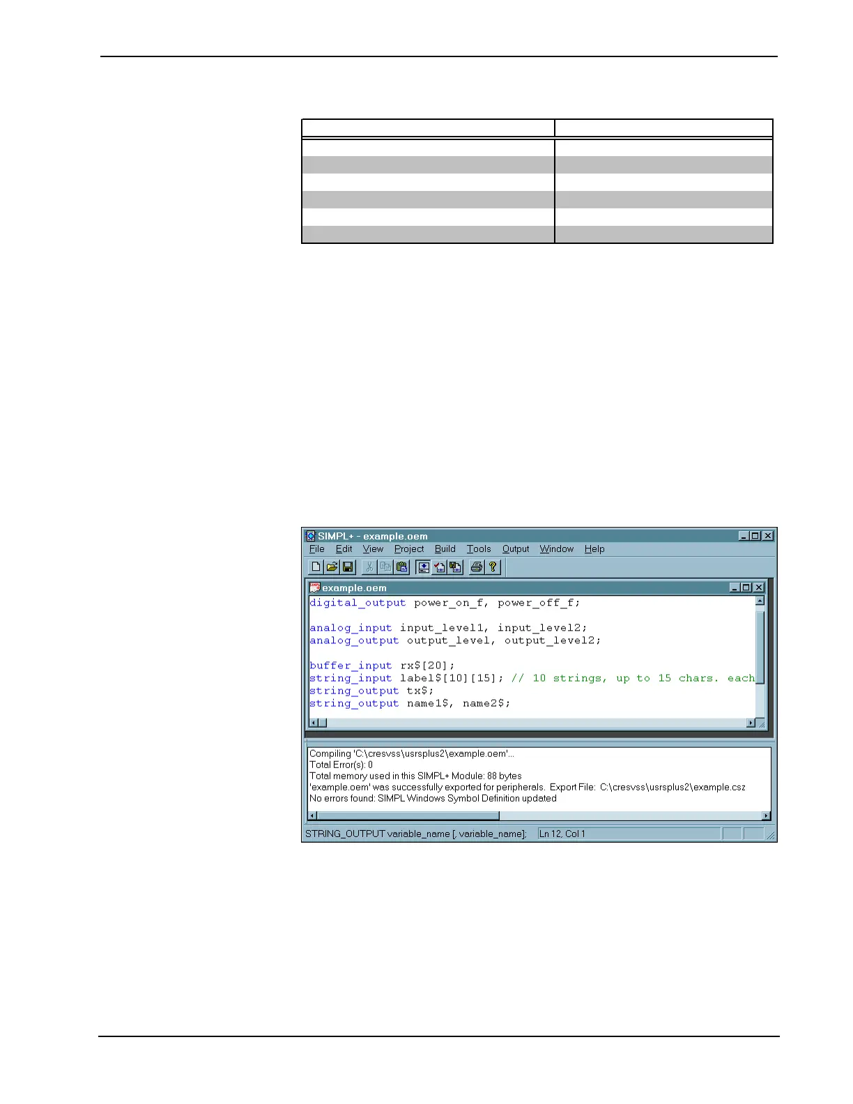
Example Program
For example, consider the illustrative example where the SIMPL+ interface to a
particular device is defined.
SIMPL+ Example
Refer to the following illustrations for the CEN-OEM symbol definition of the
digital, analog, and serial signal lists in Detail View of SIMPL Windows' Program
Manager.
Operations Guide - DOC. 8148 Ethernet OEM Module: eServer™ • 21