EasyManua.ls Logo

CrimeStopper SP-101 - User Manual

CrimeStopper SP-101
17 pages
Print Icon
To Next Page IconTo Next Page
Loading...
1
SP-101
REMOTE CONTROL ALARM SYSTEM
INSTALLATION & OPERATING INSTRUCTIONS
INTRODUCTION
CONGRATULATIONS on your choice of a ā€œSecurity Plusā€ Remote Alarm System by Crimestopper Security
Products Inc. This booklet contains the information necessary for installing, using, and maintaining your alarm
system. If any questions arise, contact your installation dealer or Crimestopper Security Products Inc. at the
Tech Support number below.
This installation book is designed for the installer or individual with an existing understanding of automotive
electrical systems, along with the ability to test and connect wires for proper operation. To ease installation,
we suggest that you READ THIS MANUAL before beginning your installation. This book is provided as a
GENERAL GUIDLINE and the information contained herein may differ from your vehicle.
TECH SUPPORT
Mon-Fri 8:00 AM-4:30 PM Pacific Time
www.crimestopper.com
Phone (800) 998-6880
FAX (805) 581-9500
REV. A 03.2010
This device complies with FCC Rules part 15. Operation is subject to
the following two conditions: 1) This device may not cause interference,
and (2) this device must accept any interference that may be received,
including interference that may cause undesired operation. The
manufacturer is not responsible for any radio or TV interference caused
by unauthorized modification to this equipment. Such modification
could void the user's authority to operate the equipment.
Question and Answer IconNeed help?

Do you have a question about the CrimeStopper SP-101 and is the answer not in the manual?

Summary

Installation Cautions and Warnings

Control Module Mounting Procedures

Component Mounting Guide

System Wiring Connections

Green Wire: Negative Door Trigger

Identifies the wire for negative door trigger detection when doors are open or closed.

Purple Wire: Positive Door Trigger

Identifies the wire for positive door trigger detection when doors are open or closed.

Yellow Wire: Ignition Switched 12 Volts

Connects to the ignition wire for 12V power during 'ON' and 'START' positions.

Black Wire: System Chassis Ground

Connects the system to the vehicle's chassis metal for a secure ground.

Blue Wire: Negative Hood;Trunk Trigger

Input trigger for hood or trunk pin switches that read ground when open.

Orange Wire: Negative Armed Output;Starter Disable

Optional output for starter disable or activating other devices when system is armed.

Power Door Lock Wiring Diagrams

Remote Transmitter Programming

Option Programming Chart

Operating Instructions

Alarm Triggering and Reset

Handles intrusion detection, trigger reset, and disarming during triggered state.

Emergency Override & Disarm

Disarms the system using the ignition and override/program button without a transmitter.

Valet Mode Operation

Disables alarm functions for service; entered/exited via ignition and override/program button.

Pre-Warning Shock Protection & Sensor Adjustment

Provides initial warning chirps for light impacts and full alarm for hard impacts.

Carjack Protection Modes

Active Carjack Protection

Initiates a carjack sequence upon ignition and door events, confirmed by button press.

Passive Carjack Protection

Initiates carjack sequence automatically after ignition and door events without manual input.

Full-Time Carjack Protection

Initiates carjack sequence on every ignition cycle and door event.

Overview

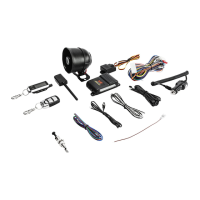
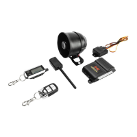
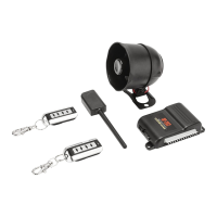
This document describes the Crimestopper SP-101 Remote Control Alarm System, a "Security Plus" system designed for automotive security. It provides comprehensive instructions for installation, operation, and maintenance.

Function Description:

The SP-101 is a remote control alarm system for vehicles, offering various security and convenience features. Its primary function is to protect the vehicle from intrusion and theft through active and passive arming, siren alerts, and starter disable capabilities. It also includes features for remote door locking/unlocking, trunk release, and car finder functions. The system is designed to be user-friendly with remote transmitter control and a valet mode for temporary disabling.

Important Technical Specifications:

  • Power Input: 12V (15 amp fuse recommended, connected to vehicle battery positive terminal).
  • Siren Output: (+) 3 Amp Max.
  • Flashing Light Outputs: Two 12V outputs, 7.5 Amp each (separate 7.5 Amp fuse for each circuit recommended).
  • Negative Armed Output / Starter Disable: (-) 500mA Ground (optional, requires relay for starter kill).
  • Negative Aux Remote Output 1: (-) (optional, may require relay for 12V circuits).
  • Negative Horn Pulse Output: (-) (optional, may require relay for 12V horn circuits).
  • Door Lock/Unlock Pulse Time: Programmable (0.75 sec. or 3 sec.).
  • Transmitter Battery: GP27A (Mini 12 volt Battery).
  • FCC Compliance: Complies with FCC Rules part 15. Operation is subject to two conditions: (1) device may not cause harmful interference, and (2) device must accept any interference received, including interference that may cause undesired operation. Unauthorized modifications could void user's authority to operate equipment.

Usage Features:

  • Active Arming: Press Button #1 (Lock Symbol) on the transmitter to arm the alarm, lock doors, and disable the starter (if installed). A single siren chirp and one light flash confirm arming. The system fully arms after a 5-second delay.
  • Silent Arming: Press Button #3 (X Symbol) on the transmitter to silently arm the alarm and lock doors. Only lights will flash once.
  • Passive Arming: If programmed (Option #2 ON), the system automatically arms 40 seconds after the ignition is turned off and the last door is closed. The LED flashes rapidly during the countdown. If a door is reopened, the system waits for the door to close before arming. Doors will lock if passive locking is selected.
  • Disarming: Press Button #2 (Unlock Symbol) on the transmitter to disarm the alarm and unlock doors. Two siren chirps and two light flashes confirm disarming. The LED stops flashing, and the dome light turns on (if installed).
  • Silent Disarming: Press Button #3 (X Symbol), then Button #2 (Unlock Symbol) on the transmitter. Only lights will flash twice.
  • Car Finder Mode: When armed, press Button #1 (Lock Symbol) to make the siren chirp once and lights flash 10 times.
  • Silent Car Finder Mode: When armed, press Button #3 (X Symbol) to make parking lights flash 10 times.
  • Remote Panic Protection: Press and hold Button #1 for at least 3 seconds to sound the alarm. Press Button #1 again to reset.
  • Trunk Hatch Pop (Optional): Press Button #4 (Trunk Symbol) for at least 1 second. If the system is armed, this may or may not trip the alarm depending on programming option #7.
  • Emergency Override & Disarm: If the transmitter is lost or not working, open the door (alarm will sound), turn the ignition ON, and press the override/program button for 4-5 seconds until the siren stops. The alarm will disarm.
  • Valet Mode: To disable the alarm for service, turn the ignition ON and press the override/program button for 4-5 seconds until the dash LED turns solid and one siren chirp is heard. Repeat the process to exit Valet Mode (two chirps, LED off). Lock, Unlock, and AUX features remain operational in Valet Mode.
  • Prior Intrusion Alert: If the alarm was triggered in your absence, the dash LED will flash rapidly. Upon disarming, four chirps and flashes will indicate a prior intrusion.
  • Open Zone Alert & Bypass: If a faulty or open zone (e.g., door left open) is detected when actively armed, the siren and horn will chirp three times with three light flashes. The faulty zone is automatically bypassed.
  • Ignition-Controlled Doorlocks: If enabled (Option #3), doors automatically lock when the ignition is turned ON and unlock when the ignition is turned OFF.
  • Pre-Warning Shock Protection & Sensor Adjustment: A low-level shock triggers five quick siren chirps and one light flash. A hard impact triggers the full alarm. The shock sensor sensitivity can be adjusted clockwise for higher sensitivity and counter-clockwise for lower sensitivity. Green light indicates pre-warning, red light indicates full alarm trigger.
  • Carjack Protection (Active, Passive, Full-Time):
    • Active Carjack: Enabled via programming (Option #10). With ignition ON, press Button #2 (Unlock Symbol). Parking lights flash twice. After 90 seconds, a Carjack Cycle begins (20 seconds pre-warning chirps, then full system activation for 5 minutes). Reset by turning ignition ON and pressing Button #2 again.
    • Passive Carjack: Enabled via programming (Options #9 & #10). With ignition ON, opening a door initiates the Carjack countdown. After 90 seconds, a Carjack Cycle begins. Reset by turning ignition ON, closing doors, and pressing the override/program button three times.
    • Full-Time Carjack: Enabled via programming (Options #9 & #10). Every time the ignition is turned ON or a door is opened and then closed with the ignition ON, a Carjack countdown begins. After 90 seconds, a Carjack Cycle begins. Reset by turning ignition ON, closing doors, and pressing the override/program button three times. This mode requires resetting every time the key is turned on or a door is opened/closed with ignition on, before entering Valet Mode, or before programming.

Maintenance Features:

  • Transmitter Battery Replacement: Uses a GP27A (Mini 12 volt Battery).
  • Factory Default Reset: Options can be instantly restored to factory default values by turning ignition ON, pressing the override/program button five times, then pressing Button #3 on the remote. The system will chirp and flash lights four times, then turn ignition OFF.
  • Wiring Diagram: A detailed wiring diagram (SP-100) is provided for installation and troubleshooting.
  • Tech Support: Crimestopper Security Products Inc. offers tech support Mon-Fri 8:00 AM-4:30 PM Pacific Time via phone (800) 998-6880 and FAX (805) 581-9500, and online at www.crimestopper.com.

Installation Cautions & Warnings:

  • DO NOT mount the control unit in the engine compartment or where wiring can become entangled with moving parts.
  • Mount the control module in a concealed location, routing the antenna wire away from metal and other wires. Do not alter antenna wire length or ground it.
  • WE RECOMMEND using a VOLT/OHM METER for testing circuits to avoid damage to vehicle computer systems.
  • DO NOT exceed maximum output ratings. Measure current loads with an amp-meter if unsure.
  • WE RECOMMEND removing the main system fuse before jump starting, using a battery charger, or changing the battery to prevent damage from voltage surges.
  • DO NOT route wiring where it may become entangled with brake/gas pedals, steering column, or other moving parts.
  • Consult vehicle manufacturer cautions regarding electrical service (AIR BAGS, ABS BRAKES, ENGINE COMPUTERS, BATTERY, etc.).
  • Mount the siren under the hood with the open end facing downward.
  • Mount the shock sensor with wire ties or screws to an under-dash harness or panel.
  • Mount the LED status indicator in a visible location.
  • Mount the Valet/Override/Program push-button in a hidden but accessible location (REQUIRED for emergency disarm, programming, and Valet Mode).

CrimeStopper SP-101 Specifications

General IconGeneral
BrandCrimeStopper
ModelSP-101
CategorySecurity System
LanguageEnglish

Related product manuals