Do you have a question about the Crompton integra 1530 and is the answer not in the manual?
Basic information for interfacing the Integra to a Modbus network.
Details 3X register addresses and values for measured/calculated electrical quantities.
Lists holding registers for instrument configuration settings via Modbus protocol.
Summarises Modbus control of analogue outputs and user settings for output ranges.
Integra as an N2 Vendor device connecting to Metasys N2 Bus.
Specifies Metasys OWS software and NCM versions for integration.
Contact information for Johnson Control Systems support.
Support for Integra operation available via local sales and service.
Key considerations for integrating Crompton equipment into a Metasys Network.
Table mapping Metasys N2 addresses to Integra parameters and units.
Information on accessing the GSD file for Profibus interface configuration.
Explains IEEE floating-point data transfer format for Profibus.
Describes accessing single parameters via a Control module in Profibus.
Describes the functionality of the PLC Function Block for Profibus communication.
Information on accessing the XIF file for LonWorks interface configuration.
Overview of LonMark Objects for Integra network interface and device profiles.
Details the Node Object and its components for LonWorks interface.
Details the Voltmeter object and its network variables for LonWorks.
Details the Ammeter object and its network variables for LonWorks.
Details the Energy Meter object and its network variables for LonWorks.
Details the Power Meter object and its network variables for LonWorks.
Details the Demand Ammeter object and its network variables for LonWorks.
Details the Demand Power Meter object and its network variables for LonWorks.
Details the Power Quality Meter object and its network variables for LonWorks.
Addresses common issues with the LonWorks interface functionality.
| Brand | Crompton |
|---|---|
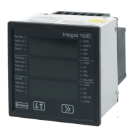
| Model | integra 1530 |
| Category | Measuring Instruments |
| Language | English |