Do you have a question about the Crompton SL1-01 and is the answer not in the manual?
Instructions for installing CTs, ensuring correct orientation and system connection.
Visual diagrams illustrating CT orientation for Category 1 and Category 2.
Outlines setup and cable requirements for CTs from the same direction/category.
Outlines setup and cable requirements for CTs from different directions/categories.
Notes the Integra 1221 meter has only one CT input.
Instructions for installing CTs, ensuring correct orientation and system connection.
Visual diagrams illustrating CT orientation for Category 1 and Category 2.
Outlines setup and cable requirements for installations with a single CT.
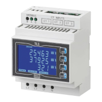
This document provides installation guidelines for Crompton Instruments DL3N1 Current Transformers (CTs) when used with Integra DL1-01, TL1-01, and INT-1221 series multi-function meters. It outlines the correct orientation of the CTs, cable types, and meter programming settings to ensure accurate measurements.
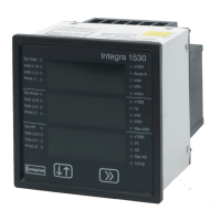
The Crompton Instruments DL3N1 CTs are designed to work in conjunction with Integra multi-function meters (DL1-01, TL1-01, and INT-1221) to measure electrical parameters in a system. These CTs transform high primary currents into lower, measurable secondary currents, which are then fed into the Integra meters for display and analysis. The Integra meters are multi-function devices capable of measuring various electrical quantities such as voltage, current, power, energy, and frequency. The correct installation and configuration of the CTs are crucial for the accurate operation of the entire measurement system.
The guide differentiates between two main categories of installations based on the CT orientation: Category 1 and Category 2. Category 1 installations involve CTs where the P1 side (primary side) faces the "Line side" of the system, and the P2 side faces the "Load side." Category 2 installations involve CTs where the P1 side faces the "Load side" and the P2 side faces the "Line side." This distinction is critical for determining the correct wiring and meter programming.
For the DL1-01 and TL1-01 meters, the guide covers scenarios where all CTs are from the same direction/category (either all Category 1 or all Category 2) and scenarios where CTs are from different/mixed directions/categories. The INT-1221-S-010 meter, being a newer version, is specifically noted to have only one CT input, simplifying its installation considerations.
The installation process is streamlined into a few key steps:
CT Orientation: Always install the DL3N1 CT with the P1 side facing the "Line side" of the system. This is a fundamental rule that applies to all installations, regardless of the specific meter or category.
Figure Selection: Refer to the provided "CURRENT TRANSFORMER ORIENTATION CHART" which illustrates different CT configurations (Figures A, B, C, D). Identify the figure that matches your specific installation requirement. Figures A and B represent Category 1 installations, while Figures C and D represent Category 2 installations.
Table Reference and Configuration: Once the appropriate figure (A, B, C, or D) is identified, consult the relevant tables to determine the required cable type and meter programming settings.
*   **For INT-1221-S-010 Multi-Function Meter (new version):**
    *   This meter has only one CT input.
    *   If your installation uses a single CT from Category 1 (Figure A or B), refer to Table 4. This table specifies a "WHITE" cable type and a "TOP" setting.
    *   If your installation uses a single CT from Category 2 (Figure C or D), refer to Table 5. This table specifies a "WHITE" cable type and a "BOT" setting.
The "CT FRAME SIZE" column in all tables is listed as "ALL," indicating that these guidelines apply universally across different physical sizes of the DL3N1 CTs. The "CT FIGURE #" column helps to cross-reference the visual diagrams with the correct table entries.
The "CABLE TYPE" refers to the specific wiring color code that must be used for the secondary connections of the CTs to the meter. The "SETTING" refers to a programmable parameter within the Integra meter that must be configured to match the CT orientation and wiring. This setting typically compensates for the phase relationship of the current signal based on how the CT is installed.
The visual diagrams clearly label the "LINE SIDE" and "LOAD SIDE" of the system, as well as the P1 and P2 terminals of the CT, and the N, E, S, P terminals of the meter. Arrows indicate the direction of current flow and the orientation of the CT. The "TE connectivity" logo on the diagrams suggests that the meters or components may be part of a broader TE Connectivity ecosystem.
While the document primarily focuses on installation, the clear and structured approach to wiring and programming inherently contributes to ease of maintenance. By following these guidelines, installers can:
The document itself serves as a critical maintenance tool, providing a reference for verifying existing installations or for re-configuring systems after component replacements. The revision number "rev15.xlsx" indicates that this is a living document, subject to updates and improvements, which is a good practice for ongoing product support and maintenance. Contact information for "COLTERLEC™" is provided for further support, indicating a channel for technical assistance should complex maintenance issues arise.
| Model | SL1-01 |
|---|---|
| Measurement Range | 30dB to 130dB |
| Power Supply | 9V battery |
| Frequency Weighting | A and C |
| Time Weighting | Fast & Slow |
| Display | LCD |