At this point, the power, ground, remote, and speaker wires should be run to the general location of where the amplifier is to be mounted
. If the wires are to be hidden u
nder
the carpet, you now need to cut a slit for them to come throug
h. To do this, place th
e amplifier in the location it is to
be mounted to verify where the slits need to
be. Make
sure that there will not be
a conflict with the mounting of the amplifier and the wires. Pull th
e wires through the slit to the terminals leaving approximately 6" (150mm) of
slack and cut the wires to an equal length. Loca
te the spade connectors supplied with the amplifier
. Strip approximately 1/2" inch (12mm) of insulation from the end of
each
wire. Crimp the spade connectors onto the stripped
end of the wire. Loosen the terminal screws on the amplifier. Insert the wires into the proper termin
als and tighten the
screws securely. Check your connections by giving the wires a slight tug.
NOTE: Not all models have screw type conn
ectors. Other models use "Discrete Mount" connectors which
require bare wire installation (no con
nector needed).
CONNECTING THE WIRES
LOAD
Please be aware of the m
inimum impedance you may apply to your particular model amplifier
. See chart below for mo
re information. Any lower impedanc
e than the minimum
can send the amplifier into curr
ent protection or poss
ibly damage the circuitry. To prevent damage, use the follo
wing formulas to help you figur
e out the load you are placing
on your amplifier. If you have any difficulties, please contact y
our local Crossfire dealer or Crossfire's Technical
Assistance at
(562)906-0800.
SPEAKER OUTPUT
WIRING
Always choose speaker wire wisely. Make
sure that the wire
is appropriate for the spea
ker you are applying it to. It is hig
hly recommended not to use an
ything smaller than
16awg. Consult your dealer.
As with the power wires, use cau
tion around sharp corners or body part
s that may easily cut through the insulation on the wir
e. If running into the door
s, it is important to
use a protective boot in the door jam to
protect the wire from being pinched as well as k
eeping water or moisture from entering
the vehicle. Use the factory boots whenever
possible. And always make sure the wire is out
of the way of the window track.
To connect the wire to the spea
ker, strip off approximately 1/2" inch (12mm)
of the insulation and terminate
the wires using insulated speak
er terminals (not
supplied) or by
soldering the connection to the
loudspeaker. Be sure that the pola
rity at the loudspeaker is correct.
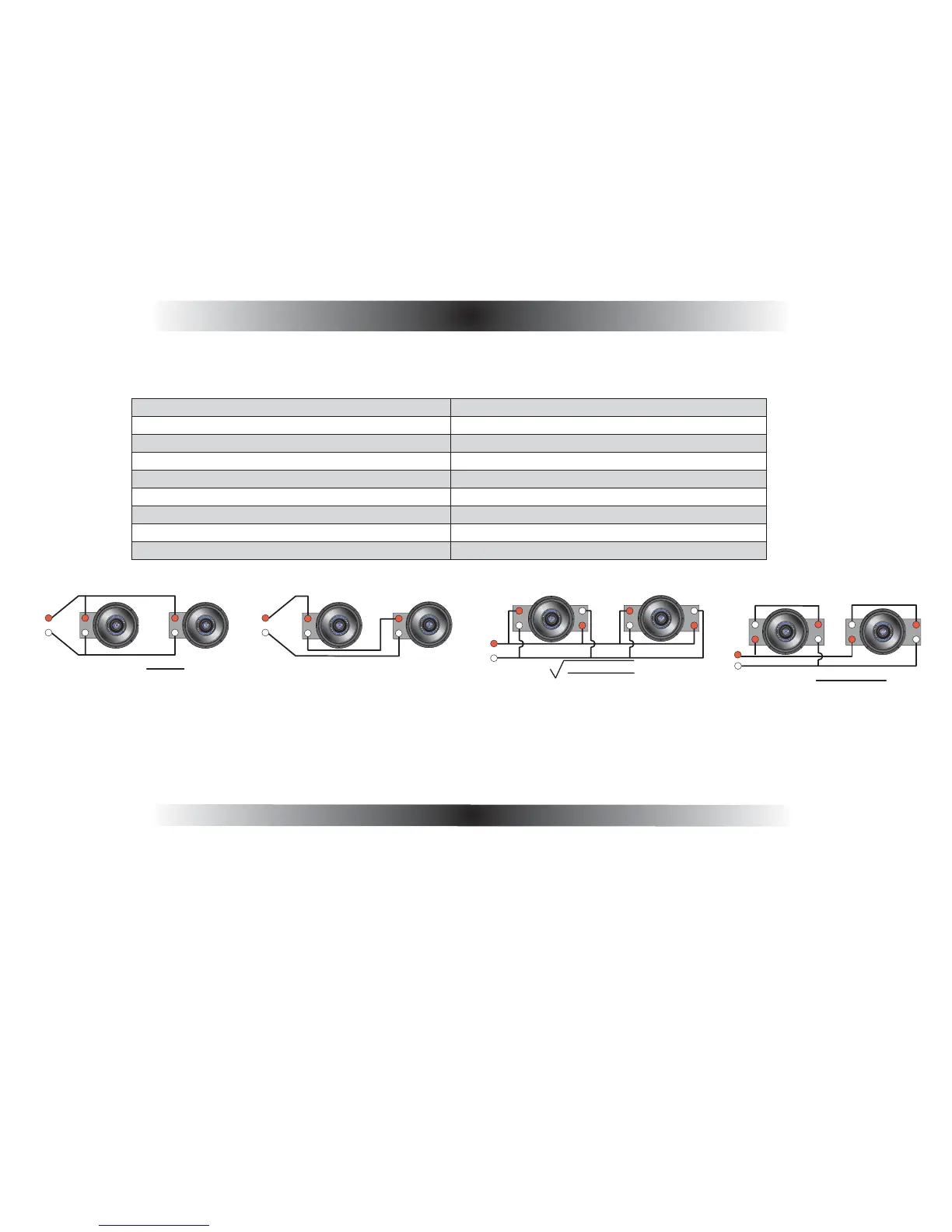
Series/Parallel
Wiring Dual Voice Coil
R
A
B
C
D
(A+B) x (C+D)
A + B + C + D
=R
Equation:
Series Wiring
A
B
R
Equation: A+B =R
Par
allel Wiring
A x B
A + B
=R
Equation:
A
B
R
(A x
B)(C x D)
(A+B)+(C+D)
Parallel Wiring, Dual Voice Coil
R
A
B
C
D
=R
Equation:
MODEL STEREO MONO MODEL STEREO MONO
VR142 2 Ohm 4 Ohm VR404 2 Ohm 4 Ohm
VR202 2 Ohm 4 Ohm VR804 2 Ohm 4 Ohm
VR302 2 Ohm 4 Ohm VR705D(F&R) 2 Ohm 4 Ohm
VR402 2 Ohm 4 Ohm (Sub) N/A 2 Ohm
VR602 2 Ohm 4 Ohm VR300D N/A 2 Ohm
VR1202 2 Ohm 4 Ohm VR600D N/A 1 Ohm
VR401 N/A 2 Ohm VR1000D N/A 1 Ohm
VR354 2 Ohm 4 Ohm VR2000D N/A 2 Ohm