Bridge Settings and Wiri
ng
LOW IN
R
L
LEVEL
HPF FULL LPF
OFF ON
MASTER
IN
OUT
INVERT
SUB
SONIC
50 250
LPF
LINE OUT
REMOTE
CROSS
OVER
SLAVE 0 180
From
Source
All Preamp functions of
the slave amplifier are
non-functional. The M
aster
amplifier controls all level
and crossover functions.
MASTER
Amplifier
Slave
Amplifier
"Preamp Settings"
LOW IN
R
L
LEVEL
HPF FULL LPF
OFF ON
MASTER
IN
OUT
INVERT
SUB
SONIC
50 250
LPF
LINE OUT
REMOTE
CROSS
OVER
SLAVE 0 180
Must be set to
Master 0 or 180
Do not use
this section
Must be set
to Slave
MASTER
Amplifier
SLAVE
Amplifier
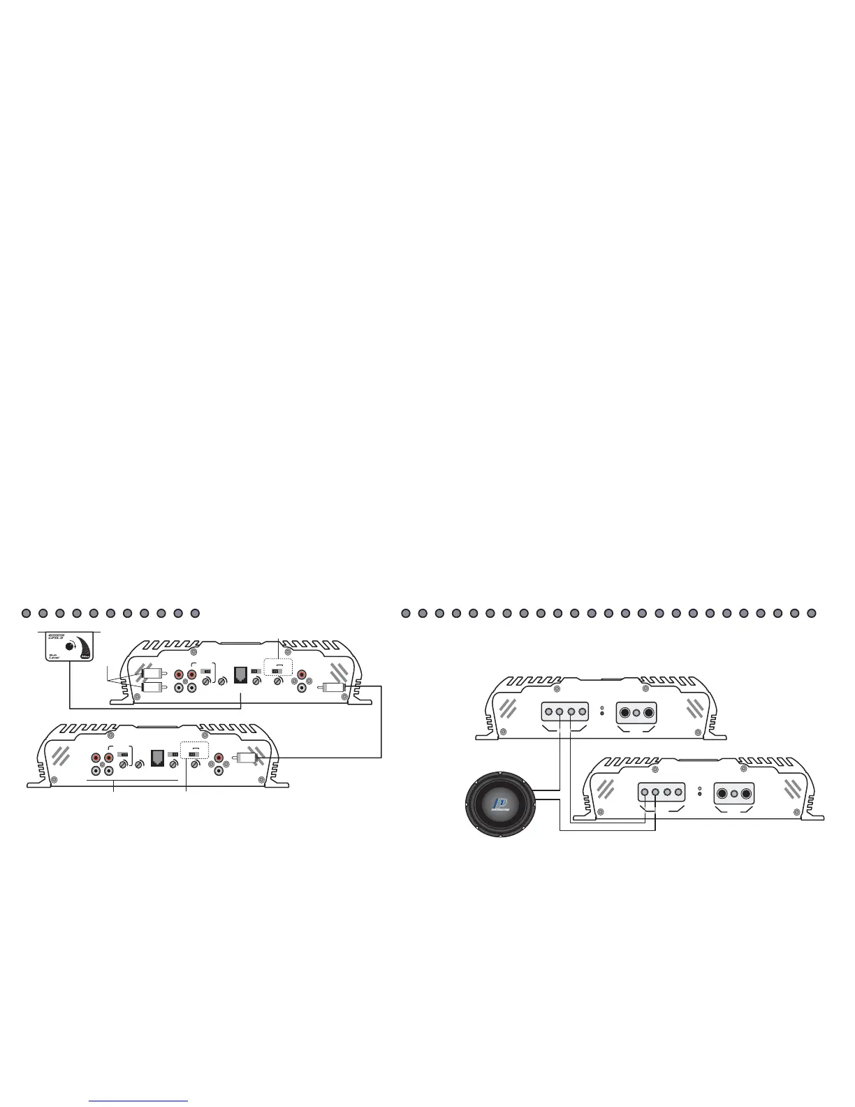
"Bridge Wiring"
It is very important that
a negative of each
amplifier
is connected as shown
+
+
-
SPEAKER
POWER
+12
REM
GND
PWR
PRT
-
+
+
-
POWER
+12 REM
GND
PWR
PRT
-
-
+
SPEAKER
"Strapping" Two VR-600Ds or Two VR-1000Ds
Bridging the two like amplifiers together is fairly easy. Study the following instructions as well as the diagrams on PG-10 to assure proper connections. If you experience any
difficulties, please contact Crossfire's Technical Assistance at 562-906-0800.
BRIDGING CIRCUIT (Invert output)
The internal bridging module can only be used when a pair of either VR1000Ds or VR600Ds are used. Bridging allows for the two amplifiers to be run in series and achieve
double the output into one load. However, this does change the minimum impedance stability to 2ohms. Bridging the amplifiers should only be done if the proper
impedance cannot be achieved with the amplifiers separated.
It is very important to set the Master/Slave control on the amplifier whether you are using the bridging module or not. If the settings are in the wrong position, the
amplifier(s) may not work. There are three settings for this control: Master 0, Master 180, Slave. Use the following to determine what position to set your amplifier(s) in.
For further reference, please review the drawings following.
Master 0:
this setting will maintain the same phase as the signal applied to it.
1. Use this setting if the amplifier is not bridged with another amplifier.
2. When bridging the amplifiers, use this setting only on the amplifier that is connected to the head unit.
Master 180:
this setting will reverse the phase 180 degrees of the signal input into the amplifier.
1. Use this setting if the amplifier is not bridged with another amplifier and the subwoofer(s) are out of phase with the satellite speakers in the vehicle.
2. When bridging the amplifiers, use this setting only on the amplifier that is connected to the head unit. Only apply this if the subwoofer(s) are out of phase with the
satellite speakers in the vehicle.
Slave:
this setting limits the controls of the secondary amplifier in a bridged pair.
1. Use this setting only on the second amplifier in a bridged pair. All crossover, subsonic and level controls of this amplifier will be bypassed. The amplifier set on one of the
two Master settings will then control each of the preamp functions for both amplifiers.
SUBSONIC FILTER
The subsonic filter is used to reduce the amount of low frequency harmonics and/or subsonic noise picked up in audio systems. Both of these can be damaging to subwoofers
and possibly the amplifier(s). As well, harmonics and subsonic noise can cause the amplifier(s) to pull excess power from your electrical system.
This filter is switchable, ON/OFF, and variable from 20Hz to 50Hz. The subsonic filter is switchable as every system is different. For most people it is desirable to have the
filter ON. However, if you have an outright SPL system, it may be beneficial to turn OFF the subsonic filter because harmonics can actually increase the sound pressure in
many cases. So what frequency should you set the subsonic filter at? For most applications it is desirable to leave this between 20Hz and 30Hz. If you are using a ported
enclosure designed for SPL, yet you are using the system on a daily basis, a higher filter frequency may be desired. This will allow the enclosure to be tuned higher and
reduce the chance of the woofer to becoming non-linear and destroying itself.
F
E
A
T
U
R
E
S
SPECIFICATIONS
IMPORTANT
Please read all instructions before installation!
MOUNTING
Tab Installation Input Sensitivity
L R
LOW IN
R
50Hz 150Hz
HIGH IN
CONNE
CTI
NG
T
HE
W
I
RE
S
S
P
E
A
K
E
R
O
U
T
P
U
T
W
I
R
I
N
G
D
I
A
G
R
A
M
S
W
I
R
I
N
G
D
I
A
G
R
A
M
S
C
O
N
T
I
N
U
E
D
PREAMP FEA
TURES
SIGNAL INPUT
S
VR AMPLIFIERS