Do you have a question about the Crown Boiler AWR Series and is the answer not in the manual?
Inspect shipment for damage and file claims promptly within sixty days.
Install according to manual, local codes, NFPA 54, and ANSI/ASME CSD-1 standards.
Verify gas configuration (Natural/LP) and ensure correct orifice for altitude above 2000ft.
Observe minimum clearances from combustibles and walls, including service clearances.
Install on a hard level surface, avoid flammable vapors, dust, carpeting, wet areas, and locate near chimney.
Details on calculating and providing air for combustion via indoor infiltration.
Steps for calculating required air volume and providing openings for indoor combustion air.
Requirements for supplying combustion air directly from outdoors via ducts or openings.
Using a blower system to supply combustion air, including sizing and interlocking requirements.
Lists approved chimney types (Type B/L, Masonry) and vent connectors (Type B/L, Single Wall).
Sizing requirements for chimneys and vent connectors according to the National Fuel Gas Code.
Guidelines for using exterior chimneys and installing listed power venters with interlocks.
Detailed instructions for installing the supplied vent damper, including connections and mounting.
Mount relief valve correctly and pipe discharge to a safe location.
Proper installation and sizing for circulator, expansion tank, and fill valve.
Explains the factory-supplied LWCO and requirements for manual reset LWCOs.
Install high limit, flow control, isolation valves, and drain valve as per codes and manual.
Guidelines for low temp systems (radiant) and systems prone to oxygen corrosion.
Design for adequate gas supply, connect to valve using approved methods and materials.
Procedures for protecting the gas control valve and leak testing the gas connection.
Details on 120VAC connections, dedicated circuits, service switches, and specific wire functions.
Describes low voltage connections for thermostats, limits, and the EnviraCom system.
Diagram illustrating field connections for line voltage wiring.
Diagram showing low voltage field connections for thermostats and controls.
Detailed wiring diagram for the S9361A boiler control, including all connections.
Ladder diagram illustrating the control logic and wiring sequences.
Perform initial checks, burner seating, and verify Low Water Cut-Off (LWCO) operation.
Fill system, turn on gas supply, purge lines, and verify vent system integrity.
Crucial safety precautions before lighting the pilot and operating the appliance.
Step-by-step instructions for lighting, operating, and turning off the boiler.
Adjust manifold pressure and check main and pilot burner flames for proper appearance.
Test gas valve safety shutdown, high limit, LWCO, thermostat, external safety devices, and check for system leaks.
Overview of the Honeywell S9361A integrated boiler control and its functions.
Explains how to navigate the control's modes (Status, Operating, Error, Adjustment).
Flowchart detailing navigation through Status, Operating, and Adjustment modes.
List and meaning of various status codes indicating boiler operation or faults.
Definitions and meanings of parameters displayed in Operating Mode.
Lists adjustable parameters, factory settings, and permissible ranges.
Details on adjusting parameters like High Limit, Differential, Circulator Overrun, and Thermal Purge.
Examples illustrating thermal purge behavior based on call for heat and zone settings.
Summary of circulator output based on thermostat inputs and control parameters.
Step-by-step explanation of boiler operation including vent damper and ignition sequence.
Explains the function and operation of safety controls like Blocked Vent Switch, Flame Roll-out, and LWCO.
Safety information regarding Refractory Ceramic Fiber (RCF) components.
Protective gear, handling procedures for RCF materials, and first aid steps.
Annual maintenance tasks including power off, inspecting flue passages, burners, pilot assembly, wiring, and vent system.
Detailed steps for cleaning soot deposits from the heat exchanger and flue passages.
General guidelines and precautions for troubleshooting boiler control problems.
Identifies causes and checks for a blank display on the boiler control.
List of error codes, their meanings, and possible causes for boiler control issues.
Lists common faults indicated by control displays without specific error codes.
Identifies service parts with part numbers and quantities for section assemblies and clips.
Lists part numbers for base wrapper, tray, insulation, front panel, and other base components.
Identifies gas valves, manifolds, orifices, pilot assemblies, and tubing with part numbers.
Lists part numbers for the drafthood, gasket kit, and blocked vent switch.
Identifies the integrated boiler control, transformer, LWCO, and control bracket.
Lists part numbers for rear, side, vestibule, and top jacket panels, door assembly, and logo plate.
Identifies temperature/pressure gauge, relief valve, drain valve, and vent damper with part numbers.
Lists part numbers for line voltage, low voltage, vent damper, and switch harness assemblies.
Explains derating for altitudes above 2000ft and the need for correct burner orifices.
Guidance on selecting the correct orifice size for installation altitude.
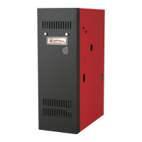
| Type | Water Boiler |
|---|---|
| Fuel Type | Natural Gas or Propane |
| Heat Exchanger Material | Cast Iron |
| Vent Type | Chimney Vent |
| Ignition Type | Electronic Ignition |