Do you have a question about the Crown PIP-AMCB and is the answer not in the manual?
Lists the key capabilities of the P.I.P.-AMCb, including crossover, EQ, and compressor functions.
Secures the PIP module to the amplifier using screws with circlips.
Holds spare crossover SIP resistors for frequency selection.
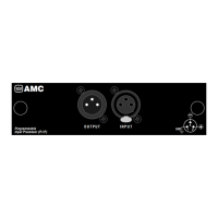
Balanced 3-pin XLR connectors for input and output, wired pin 2 high.
DIP switch for setting horn EQ shelving and low-pass roll-off frequencies.
Six-segment switch setting the threshold for the channel 2 compressor.
Jumper options for configuring the "daisy chain" output signal routing.
Jumpers for routing high/low frequency signals to amplifier channels.
DIP switch for selecting which channel's feedback drives compressors.
Six-segment switch setting the threshold for the channel 1 compressor.
DIP switch for setting the +6 dB boost frequency for vented box equalization.
SIP resistors used to set the crossover frequency; factory set to 800 Hz.
Details how to select crossover frequencies using SIP resistors and the Linkwitz-Riley topology.
Details the specific switch settings for CH1 and CH2 compressor thresholds and corresponding voltage levels.
| Brand | Crown |
|---|---|
| Model | PIP-AMCB |
| Category | Accessories |
| Language | English |