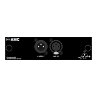
P.I.P.–AMCb
Page 14
Output Channel Control
The P.I.P.–AMCb provides several
options for routing high and low fre-
quency signals from each of its two
output channels to the amplifier in-
puts. The “CH OUT” jumpers are
used to set this (see Figure 2.1).
These jumpers can be set so that
each amplifier channel is supplied
with either the high- or low-frequency
signal. The possible configurations
are: (1) high frequencies to both
channels, (2) low frequencies to both
channels, (3) high frequencies to
Channel 1 and low frequencies to
Channel 2, and (4) low frequencies
to Channel 1 and high frequencies to
Channel 2.
IMPORTANT: If you are using the
P.I.P.–AMCb with an amplifier in ei-
ther mono mode, remove the CH2
OUT jumper. Only the Channel 1 au-
dio signal is required to drive the
amplifier during mono operation.
Compressor Control
The compressor control is a six-seg-
ment DIP switch that provides com-
plete control over the compressors’
drive circuits.
Channel 1, Channel 2 or both chan-
---
---
---
---
---
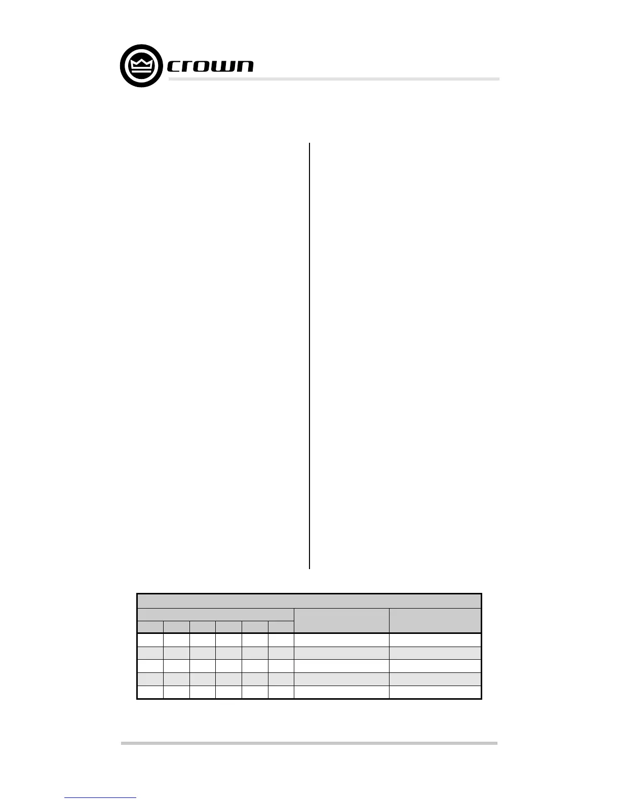
COMPRESSOR CONTROL
Switch Settings
Low Compressor
Controlled By
OFF
ON
Channel 1
Channel 2
Channel 1
Channel 2
Channel 1 or 2
ON
OFF
ON
1
ON
ON
OFF
OFF
ON
234
ON
OFF
ON
OFF
ON
56
ON
OFF
ON
OFF
ON
---
---
---
---
---
High Compressor
Controlled By
Channel 2
Channel 1
Channel 1
Channel 2
Channel 1 or 2
Fig. 3.10 Compressor Control DIP Switch Settings
nels can control the high and low fre-
quency compressors in any combi-
nation. The compressor switches
should be set based on the output
signal routing you choose (see previ-
ous section).
Often, it is desirable for the low-fre-
quency signal to control the low-fre-
quency compressor, and the high-
frequency signal to control the high-
frequency compressor. Another de-
sirable way of using the “COMP
CONTROL” DIP switch might be to
have the low-frequency signal control
both the low-frequency compressor
and the high-frequency compressor.
In this mode, the highs and lows will
be compressed equally.
Figure 3.10 shows the available set-
ups: (1) channel 1 controls the low-
frequency compressor, channel 2
controls the high-frequency com-
pressor; (2) channel 1 controls the
high-frequency compressor, channel
2 controls the low-frequency com-
pressor; (3) channel 1 controls both
high- and low-frequency compres-
sors; (4) channel 2 controls both
high- and low-frequency compres-
sors; and (5) both channels control
both compressors.
Note:
Switches 3 and 6 are unused.
 Loading...