5 V1.02
LIST OF ITEMS
Position Quantity Designation of the itme
1 1 Ball valve G1/2“, threepart, made of stainless-steel
2 1 Fastening plate
3 1 Upper plate
4 2 Thread bars
5 2 Guide bars
6 2 Wing nuts
Fastening nuts and washers
A = Counter nuts
ALIGNMENT OF THE SENSOR
Safety information must be observed.
Assembly is carried out by inserting the connection thread (1/2“ thread, SW 27) into the
connection piece of the ball valve.
Once the sensor has been aligned, the adapter sleeve must be tightened with the stipulated
torque (20 - 30 Nm - SW 17).
Attention: Alignment of the sensor must not be modified when tightening the connection
thread and adapter sleeve. In this case please check the immersion depth and alignment
again and correct if necessary. The angular deviation should not be greater than ± 2° in re-
lation to the ideal position as otherwise the measuring accuracy will decrease.
An undisturbed flow progression is achieved if the sections in front of the sensor (inlet) and
behind the sensor (outlet) are sufficiently long, absolutely straight and without any obstruc-
tions such as edges, seams, curves etc.
For more details please see the instruction manuals of the consumption sensors.
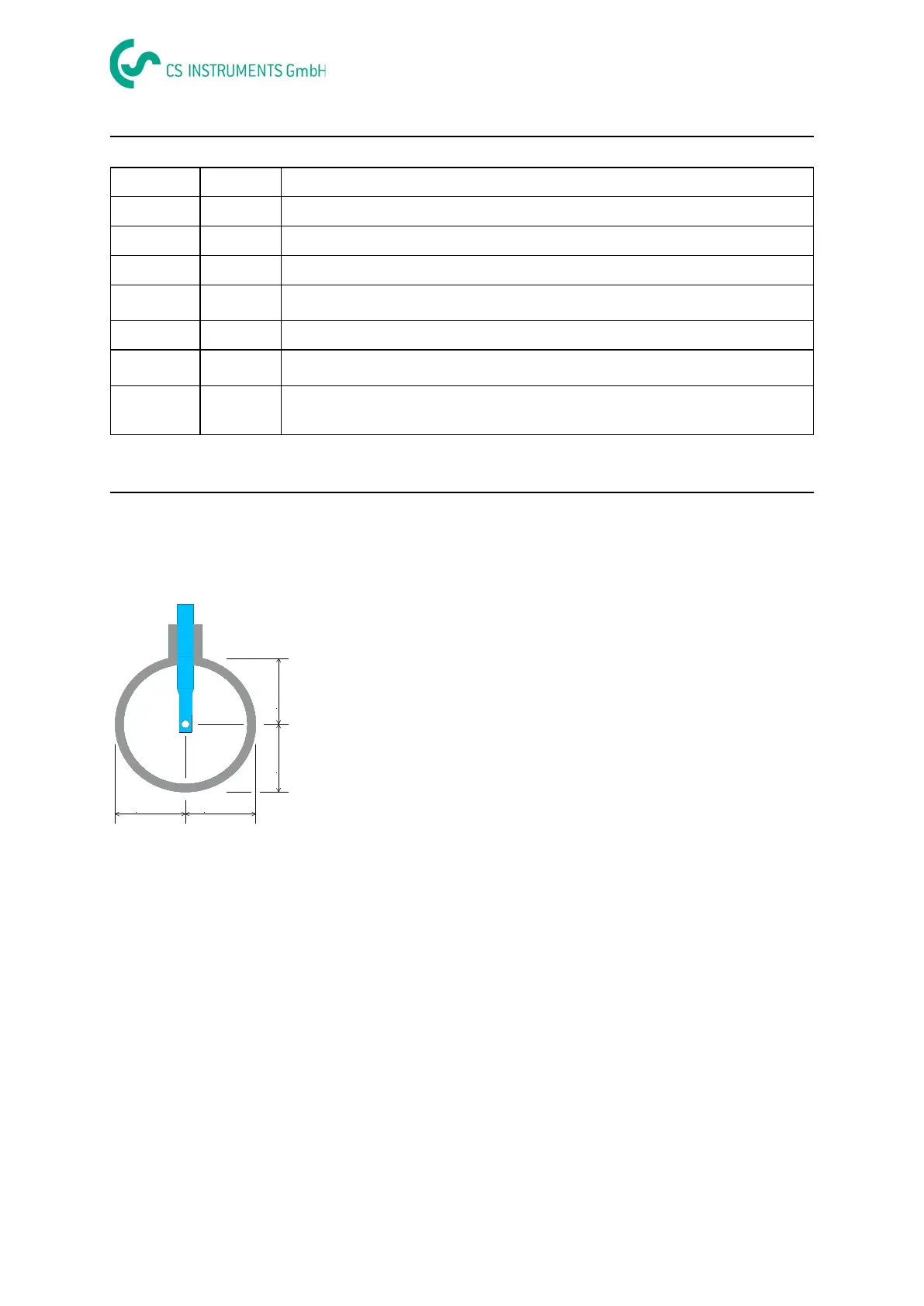
The sensor is then inserted to the required immersion
depth and aligned according to the direction of air flow as
described on page 3. A depth scale engraved on the
probe tube, a flow alignment arrow and an aligning device
will be of help to you.