Do you have a question about the CS Instruments VA 550 and is the answer not in the manual?
Explains graphical symbols used for warnings and notes in the manual.
Defines hazard levels (Danger, Warning, Caution, Note, Important) and associated risks.
Specifies the authorized applications and purpose of the flow sensor.
Outlines requirements and procedures for installing and starting up the device.
Details electrical signal outputs like Modbus, Current, Pulse, and Alarm, including output types.
Lists the available flow sensor versions and their maximum measuring ranges.
Provides full-scale flow values for the Low Speed version across various pipe diameters and gases.
Lists full-scale flow values for the Standard Version across pipe diameters and gases.
Provides full-scale flow values for the Max Version across pipe diameters and gases.
Lists full-scale flow values for the High Speed Version across pipe diameters and gases.
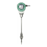
Shows physical dimensions and sensor length options for the VA 550.
Specifies requirements for pipe sizing, flanges, gaskets, and cleanliness for installation.
Details recommended minimum lengths for inlet and outlet sections to ensure measurement accuracy.
Describes how to install the VA 550 using a ball valve or a spot drilling collar.
Guides on mounting the sensor onto the ball valve and aligning it for optimal measurement.
Explains housing rotation and specifies torque values for secure assembly.
Covers cable gland ranges and connector pin configurations for various sensor versions.
Provides wiring diagrams for Power Supply, Modbus RTU, Modbus TCP, and Pulse Output.
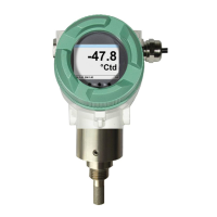
Describes the initial startup screen and main menu navigation.
Details accessing the password-protected settings menu and navigating through items.
Guides on configuring sensor parameters like tube diameter, consumption counter, and units.
Covers setting reference conditions, filter time, and averaging time.
Guides on setting the zero point and low-flow cut-off for accurate low-flow measurements.
Explains setup procedures for Modbus RTU communication protocols.
Explains setup for Modbus TCP interface, including IP address, port, and commands.
Details configuring pulse/alarm outputs, password, and language settings.
Guides on adjusting analog output scaling, auto-range, and error current settings.
Provides sensor serial number, calibration date, and live data.
Details how to change M-Bus primary address and baud rate.
| Measuring principle | Thermal mass flow |
|---|---|
| Accuracy | ±1.5% of m.v. ±0.3% of f.s. |
| Operating pressure | Up to 16 bar |
| Housing material | Stainless steel |
| Protection class | IP65 |
| Response time t90 | <1 s |
| Medium | Air, gases |
| Output signals | 4 to 20 mA, pulse, Modbus |
| Process connection | G1/2" |