Installation
VA 550 English V1.21 Page 23 of 53
6.4 Installation of the Sensor
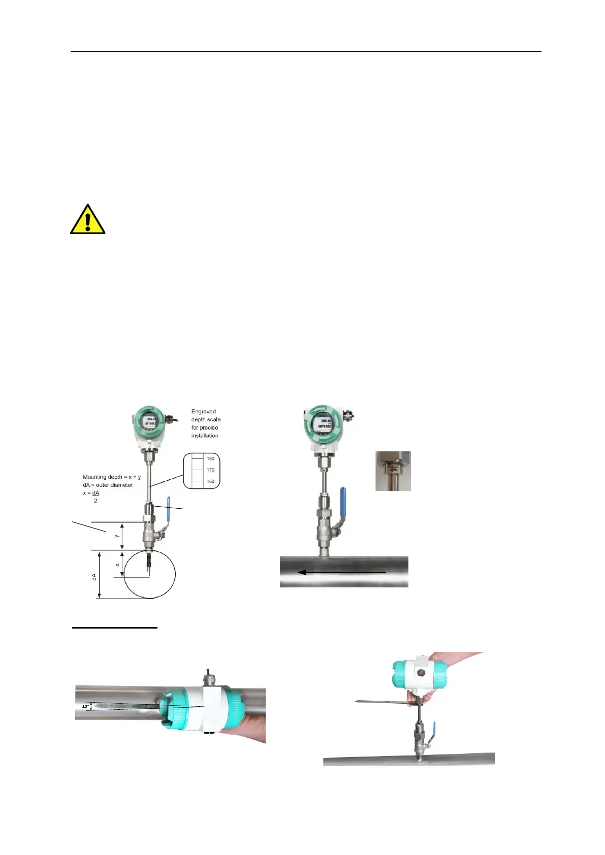
6.4.1 Mounting VA 550 onto the ball valve
• Assembly is carried out by inserting the connection thread with gasket. (G1/2“
thread, SW 32) into the connection piece (ball valve).
The sensor has be tighten by hand as far as possible and then tighten with
stipulated torque of 25-30 Nm.
It must be ensured that the installation is pressure-tight.
• The sensor is then inserted to the required immersion depth and aligned
according to the direction of the airflow.
A depth scale engraved on the probe tube, a flow alignment arrow and an
aligning device will be of help for you.
Once the sensor has been aligned the adapter sleeve must be tighten with
stipulated torque of 20-30Nm (SW 17).
Attention: Alignment of the sensor must not be modified when tightening the connection thread and
adapter sleeve. In this case, please check the immersion depth and alignment again and
correct it if necessary. The angular deviation should not be greater than 2° in relation to
ideal position as otherwise the measuring accuracy will decrease.
Calculation mounting depth: Alignment