Home
CS Instruments
Accessories
VA 550
CS Instruments VA 550 User Manual
4
of 1
of 1 rating
53 pages
Give review
Manual
Specs
To Next Page
To Next Page
To Previous Page
To Previous Page
Loading...
Connection / Wiring
VA 550 English V1.16
Page
25
of
53
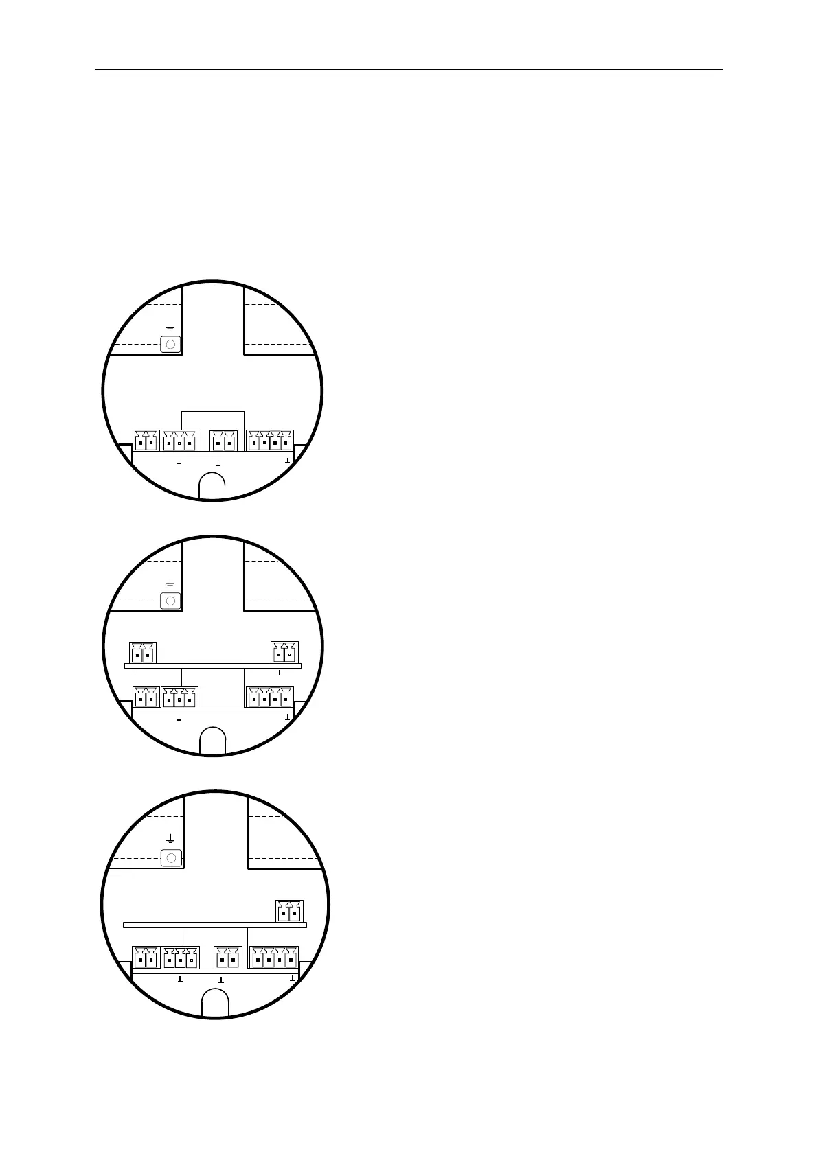
7
Connection diagram
7.1
Cable glands - c
lamping ranges
For ensuring the tightnes
s and strain re
lief, connector c
ables with the
follow
ing diameters
must be
used.
VA550 Standard cla
mping range : Ø 5
- 9mm
VA550 Ex clamping r
ange :
Ø5
-10mm
7.2
Connector pin ass
ignment
Pulse
1
2
I (4-20mA)
X1
X2
X3
1
2
GND
VB+
1
2
3
Mod(A)
1
2
3
4
Pulse
DIR
Main Board
Mod(B)
X4
Standard version with
1x analogue output
(not
galvanically
isolated)
Pulse
1
2
I (4-20mA)
1
2
X1
X2
X4
X6
X5
I (4-20mA)
1
2
GND
VB+
1
2
3
Mod(A)
1
2
3
4
Pulse
DIR
Main Board
Mod(B)
Option Board 4-20mA
Version with option
board 2x analogu
e outputs galvan
ically
isolated
Pulse
2
1
X1
X2
X4
K1
MBUS
1
2
GND
VB+
1
2
3
Mod(A)
1
2
3
4
Pulse
DIR
Main Board
Mod(B)
Option Board MBus
I ( 4...20mA)
X3
Version with option
board MBus
24
26
Table of Contents
Foreword
3
Table of Contents
4
Table of Content
5
Pictograms and Symbols
6
Signalwords According ISO 3864 and ANSI Z 535
6
Safety Instructions
7
Intended Use
8
Installation and Commissioning
8
Technical Data
9
Signal Circuits
10
Modbus
10
Current Output
10
Aktive
10
Passive
10
Pulse
10
Alarm
10
Measuring Range Flow VA 550
11
Maximum Flow Ranges „Low Speed
12
Measuring Range „Standard Version
14
Measuring Range „Max Version
16
Measuring Range „High Speed Version
18
Dimensions
20
Dimension VA 550
20
Installation
21
Pipe/Tube Requirements
21
Inlet / Outlet Runs
21
Installation VA 550
22
Welded Nipple with Ball Valve ½
22
Spot Drilling Collar with Ball Valve
22
Installation of the Sensor
23
Mounting VA 550 Onto the Ball Valve
23
Alignement Display (Housing)
24
Tightening Torques
24
Connection Diagram
25
Cable Glands - Clamping Ranges
25
Connector Pin Assignment
25
Wire Connection
27
General
27
Power Supply
27
Modbus RTU
27
Modbus TCP (Ethernet) Optional Poe
28
Pulse Output
28
Operation VA 550
29
Main Menu (Home)
30
Intialization
30
Main Menu
30
Settings
31
Sensor Setup
32
Input / Change Tube Diameter
32
Input / Change Consumption Counter
33
Definition of the Units for Flow, Velocity, Temperature and Pressure
33
Definition of the Reference Conditions
34
Setting of Zeropoint and Low-Flow Cut off
36
Modbus RTU
37
Setup
37
Modbus TCP (Optional)
38
Setup
38
Network Setup DHCP
38
Network Settings Static IP
39
Modbus TCP Settings
40
Modbus Settings (2001
41
Values Register (1001
41
Pulse /Alarm
43
Pulse Output
43
User Setup
44
Password
44
Language
44
Display / Touch
45
Advanced
45
-20Ma
46
VA 550 Info
48
Mbus
49
Change of Communication Settings
49
Coding VIF (Value Information Field)
50
Default Settings Communication
50
Default Values Transmitted
50
Supplementary Documentation
50
4
Based on 1 rating
Ask a question
Give review
Questions and Answers:
Need help?
Do you have a question about the CS Instruments VA 550 and is the answer not in the manual?
Ask a question
CS Instruments VA 550 Specifications
General
Brand
CS Instruments
Model
VA 550
Category
Accessories
Language
English
Related product manuals
CS Instruments VA 500
56 pages
CS Instruments Vortex VX 570
44 pages