Installation
VA 550 English V1.21 Page 22 of 53
6.3 Installation VA 550
The installation of the sensor is done via a ball valve ½ ".
If no valid measuring point with a ball valve ½ " is available there are following ways to set up a
measuring point.
When using the consumption sensor in systems with working pressure > 10 bar, for
safety reasons the use of a high pressure protection is required.
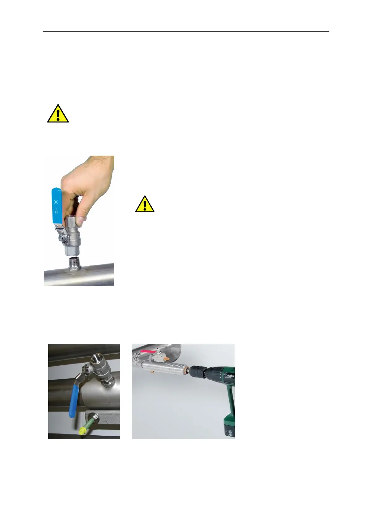
6.3.1 ½“ welded nipple with ball valve ½“
6.3.2 Spot drilling collar with ball valve
In case the system could not be shut down, means to be set depressurized, there could be used the CS
spot drilling collar (Order-No. 0530 1108) and drilling jig (Order-No. 0530 1108) to drill through the ball
valve.
Important:
Ensure that the system is in shut down,
i.e. depressurized.
Note for installation with ball valve
Ball valve R 1/2“, DN 15
Passage ball valve: Minimum Ø15 mm