Do you have a question about the CS Instruments Vortex VX 570 and is the answer not in the manual?
Important instructions for personnel performing installation and maintenance.
Responsibilities of the installer and plant operator for the device.
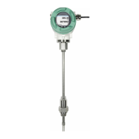
Lists the items included with the Flow-Sensor VX 570.
Details found on the device's name plate, including part and serial numbers.
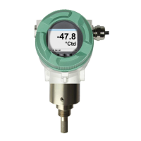
Defines the primary purpose and application of the VX 570 flow sensor.
Explains warning and information symbols used throughout the manual.
Describes the different hazard levels (Danger, Warning, Caution, Note).
Covers essential safety guidelines for operation and maintenance.
Guidelines for environmentally friendly disposal and handling.
Highlights the main features and capabilities of the VX 570.
Overview of the gas, steam, and liquid measuring ranges.
Detailed technical specifications and operating environmental parameters.
General notes on installation, storage requirements, and handling.
Guidance on safe transport and necessary pipe/tube conditions.
Specifies required straight pipe sections for accurate flow measurement.
Steps for initial system setup and device commissioning.
Provides dimensions for the intermediate flange (wafer) version.
Dimensions for the PN 16 flange version without temperature/pressure sensors.
Dimensions for PN 25 and PN 40 flange versions without sensors.
Dimensions for ANSI Class 150 and 300 flange versions without sensors.
Dimensions for the PN 16 flange version with temperature/pressure sensors.
Dimensions for PN 25 and PN 40 flange versions with sensors.
Dimensions for ANSI Class 150 and 300 flange versions with sensors.
Details on cable glands and required clamping range.
Explains the function of each pin on the connector.
General wiring practices and power supply connection details.
Wiring configurations for Modbus RTU and service interfaces.
Describes how to operate the device using optical keys.
Overview of the main menu structure and value display screens.
Explains how to access and navigate the password-protected settings menu.
How to set or view the tube diameter for measurement calculations.
Setting the consumption counter and defining measurement units.
Configuring units for flow, velocity, temperature, and pressure.
Accessing advanced settings for media conditions and filtering.
Setting reference pressure and temperature for standard volume calculations.
Configuring filter time and averaging time parameters.
Setting medium name and density for accurate measurement.
Configuring pressure type and setting pressure correction (offset).
Configuring Modbus ID, Baud rate, Parity, and Stop bit.
Lists the default factory settings for Modbus communication.
Details Modbus register addresses for configuration parameters.
Details Modbus register addresses for measured values.
Setting and changing the device password.
Choosing the display language for the device.
Adjusting backlight, dimming, screen rotation, and key lock.
Options for factory reset and extending calibration validity.
Assigning measured values (flow, velocity, temp, pressure) to analog output channels.
Configuring analog output scaling and defining error current behavior.
Viewing production data, serial numbers, and calibration details.
Displays status messages, such as calibration reminders.
Explains various error messages and their causes (e.g., Low Voltage).
Recommends a calibration interval and the process for recalibration.
Information on repair procedures and the availability of spare parts.
Guidance on calibration cycles, adjustments, and certification services.
Outlines the warranty period, coverage, and exclusions.
| Brand | CS Instruments |
|---|---|
| Model | Vortex VX 570 |
| Category | Accessories |
| Language | English |