Do you have a question about the CS Instruments FA 550 and is the answer not in the manual?
Overview of signal circuits including Modbus, Current, and Alarm.
Specifies clamping ranges for cable glands.
Details pin assignments for electrical connectors.
General guidelines and requirements for wire connections.
Configuration for Modbus TCP, PoE, and Pulse Output.
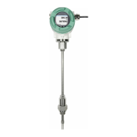
Procedure for direct installation into the process line.
Mapping of measured values to Modbus registers.
Configuration of Modbus communication parameters (ID, Baudrate, etc.).
Setting up analog scaling for Modbus communication.
Initializing the sensor upon first use.
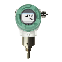
Overview of the main display screens and navigation.
Accessing and navigating the sensor settings menu.
Configuring sensor-specific parameters like units.
Defining pressure inputs for dew point calculations.
Performing one-point calibration for the sensor.
Configuring Modbus RTU communication parameters.
Setting up the optional Modbus TCP interface.
Configuring static IP settings for Modbus TCP.
Configuring alarm thresholds and hysteresis.
Setting password, brightness, and language.
Configuring the 4-20mA analog output.
Displaying sensor production and live data.
| Measuring principle | Thermal mass flow |
|---|---|
| Protection class | IP65 |
| Process connection | G 1/2" thread |
| Output signal | 4...20 mA, pulse output, Modbus RTU |
| Power supply | 24 VDC |