Electrical wiring
Page 13 FA 550 V1.00
9.3 Wire connection
9.3.1 General:
Wiring to be done in strainless state only.
Length of cable skinning to be minimized
Not used cable entries must be closed with end caps
Use of cables with cross section of >= 0.25mm²
9.3.2 Power supply
Alarm
X1
X2
X4
1
2
GND
VB+
1 2
3
Mod(A)
1 2 3 4
Âlarm
NC
Main Board
Mod(B)
1
2
I (4...20mA)
X3
NC
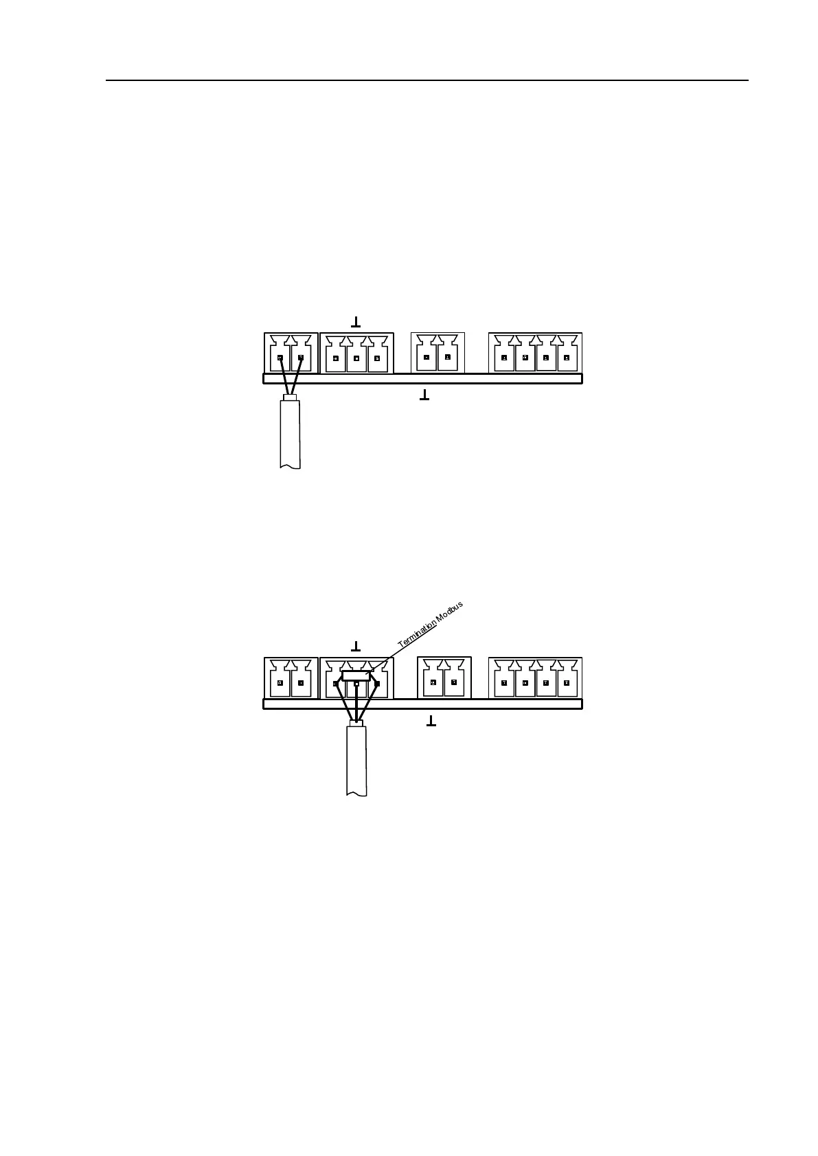
9.3.3 Modbus RTU
If the sensor placed at the end oft he Modbus system a termination is required.
Therfore the enclosed 120R resistor is to be connected at Pin 1 and Pin 3 of connector „X2“
Alarm
X1
X2
X4
1
2
GND
VB+
1 2
3
Mod(A)
1 2 3 4
Alarm
NC
Main Board
Mod(B)
120R
1
2
I (4...20mA)
X3
NC