MR-VAV-AX
4 Installation Sheet (TCON148 06/97)
Control Systems
International
®
to TCON147,
Application Specific Controller Installation Guide
.
Specifications
Dimensions
MR-AHU: 7.75" W
×
6.25" L
×
2.5" H
(197 cm
×
159 cm
× 63.5
mm)
Damper Shaft Mounting Screws
Torque Minimum: Varies according to shaft material
Torque Maximum: 30 inch-pounds
Torx head screws: 10-32 (T25)
Operating Environment
Temperature: 32
°
to 122
°
F (0
°
to 50
°
C)
Humidity: 10 to 90% RH, non-condensing
Input power: 24 VAC
±
10%, 50/60 Hz @ 7 VA plus output
load (with I/STAT)
24 VAC @ 6 VA plus output load (without
I/STAT)
Cable Requirements
MR LAN Maximum Length: 5,000 ft. (1,500 m)
22 AWG (0.324 mm
2
) shielded, twisted pair
(Belden 9184 equivalent) 5,000 feet (1,500 m)
maximum
or
24 AWG (0.206 mm
2
) shielded, twisted
pair (Belden 9841 equivalent) 4,000 feet (1,200 m).
30 pF/ft. or less between conductors, 55 pF/ft. or less
conductor to shield, 85 to 150 ohm impedance.
Inputs/Outputs
Inputs: Digital — Dry Contact, excitation 5 V at 0.5 mA
Analog — 10K Ohm NTC Thermistor, Dale
1M1002-C3 (Reference CSI TTS100 specification)
Accuracy: 1%
Resolution: 0.4% Span
Velocity Pressure Input:
Span: 0 – 1" (0 – 250 Pa) Water Column
Resolution: 0.0043" WC (1.07 Pa)
Accuracy: 5% @ 1.00" WC (250 Pa)
Outputs: 24 VAC @ 0.5A max. each output (1.5A max.)
© 1996, 1997 by Control Systems International. All rights reserved.
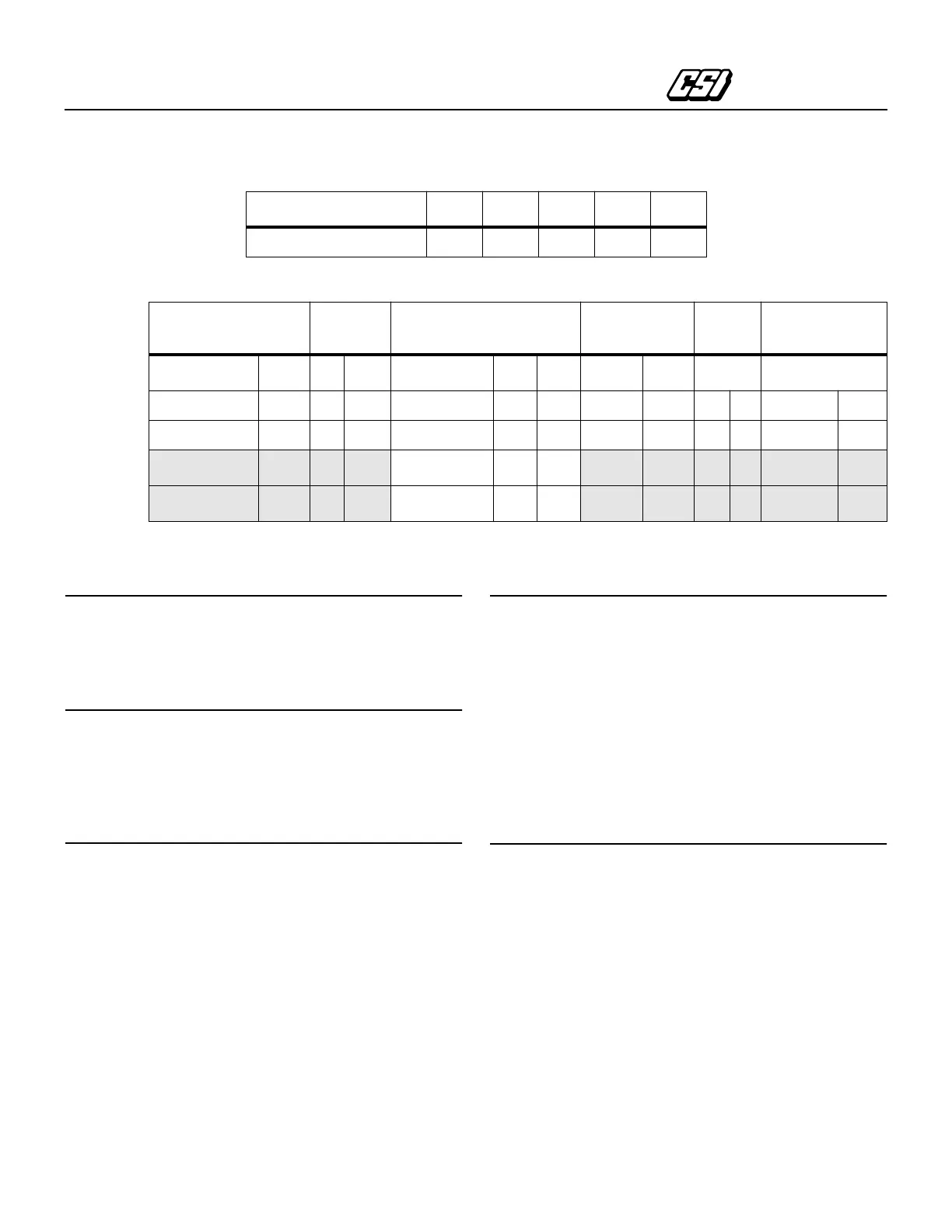
Table 1. MR-VAV-AX LAN Address
Switch Number 1 2 3 4 5
Switch Value (Switch On) 1 2 4 8 16
Table 2. DIP Switch Configuration Settings
Central Plant Heat or
Warmup Present
Fan Present Auxiliary Heating Stages Fan Type S/STAT
Damper Rotation
(Close Direction)
SW 6 SW7 SW8 SW9 SW10 SW11 SW12
No Off No Off None Off Off Series On Yes On CCW Off
Yes On Yes On 1 Heat Stage On Off Parallel Off No Off CW On
2 Heat Stages Off On
Not Available On On
 Loading...