Control Systems
International
®
MR-VAV-AX
Installation Sheet (TCON148 06/97) 3
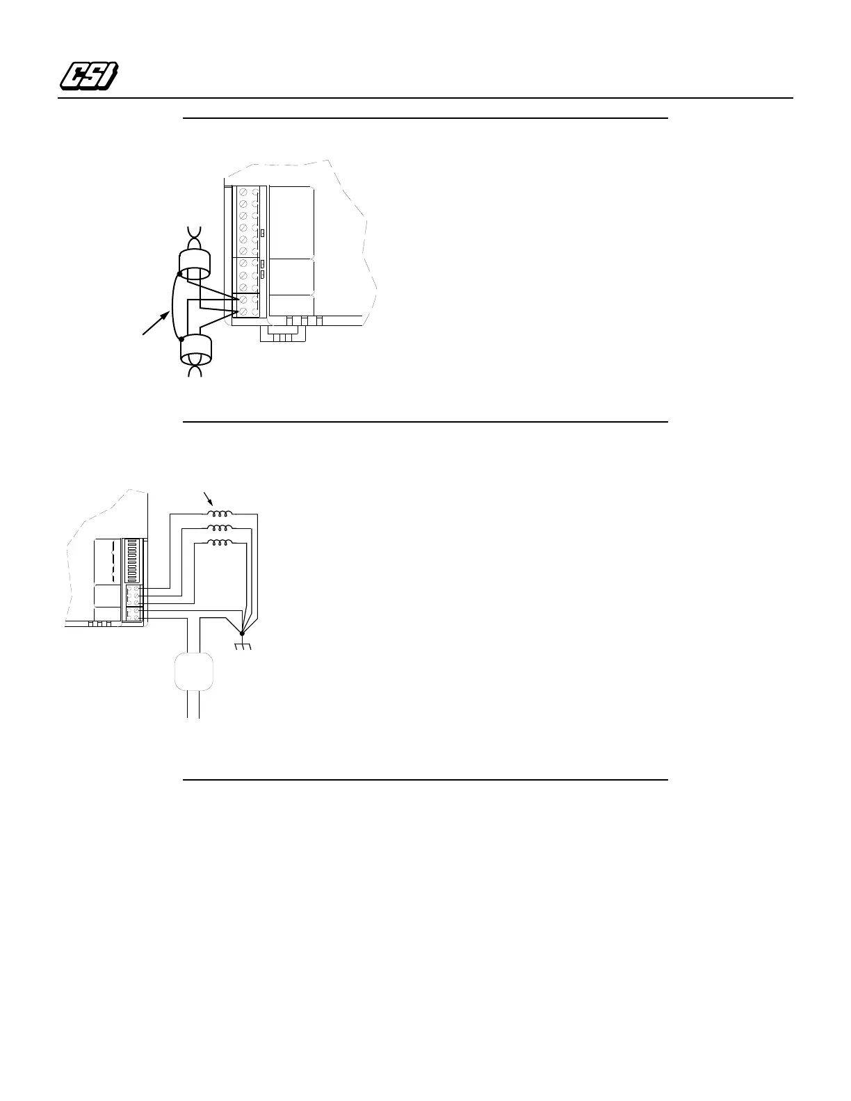
Connecting the Sub-LAN
1.
Connect the + lead of the twisted pair sub-LAN cable to
terminal TB3 – 1 (LAN+), see Figure 6.
2.
Connect the – lead of the twisted pair sub-LAN cable to
terminal TB3 – 2 (LAN –).
3.
Shield drain wire continuity must be maintained as the sub-
LAN cable passes through each MR-VAV-AX. Shield drain
wires from each controller sub-LAN cable must be twisted
together, insulated, and tied back such that wires do not
come in contact with ground or any conductive surface.
Note:
Connect the shield drain wire directly to Electrical
Service Earth Ground at
only
one end of the cable
(e.g., at the MCI, MRI, or at one MR-VAV-AX).
Auxiliary Fan and Heat Control Connections
1.
Connect one lead of the control relays to terminal TB2 – 1
(Output 1) through TB2 –3 (Output 3) as shown in
Figure 7.
2.
Connect the other lead of the control relays to earth ground
as shown.
Note:
You must establish a proper earth ground
connection point prior to connecting wires to
electrical equipment.
•
Electrical Service Earth Ground wire must be securely
connected to the equipment chassis.
•
The 24 VAC transformer secondary lead must be securely
connected to the Electrical Service Earth Ground wire.
•
The Electrical Service Earth Ground wire must be connected
to the ground terminal on the controller power input
terminal, TB1 – 2 (Ground).
Connecting the Power Supply
1.
Connect the 24 VAC input lead from a separate, isolated 24
VAC transformer to TB1 – 1 (24 VAC), see Figure 7.
2.
Connect TB1 – 2 (Ground) to earth ground using 14-AWG
wire (2.1 mm
2
). TB1 –2 connects to the same earth ground
connection as the neutral lead from the transformer.
Note:
Connecting TB1 – 2 to a chassis bonding post
separated by seams, welds, or fasteners in the metal
chassis could produce continuity ground faults.
Switch Settings
The DIP switch settings define the sub-LAN address and basic
configuration of the unit. Define the sub-LAN address using
switches 1 – 5 to set an address ranging from 0 to 31. The value
is the accumulated value of switches 1 – 5 when set to the ON
position. The ON position of the switch is away from the “Open”
label on the switch base. The operational configuration can be
initially set using the DIP switch settings in Table 2. For
information concerning specific application configurations refer
Figure 6. Sub-LAN Connections
LAN -
LAN +
GROUND
POWER
DATA
GROUND
+12V
INPUT 4
INPUT 3
INPUT 2
INPUT 1
TB3TB4TB5
LAN
Shield
+
–
Figure 7. Fan and Heat Control Connections
OUTPUT 2
OUTPUT 1
OUTPUT 3
24VAC
GROUND
12
11
10
9
8
7
6
5
4
3
2
1
TB1 TB2 SWITCHES
FUNCTION
SELECT
ADDRESS
SELECT
24VAC
Transformer
Aux/Fan/Heat
Relay Loads
24VAC @ 0.5A each (max.)
Line Voltage Input
 Loading...