Do you have a question about the CTB BKSC-4011GHX and is the answer not in the manual?
Explains the meaning of the "Danger" symbol indicating severe injury or death risk.
Explains the meaning of the "Caution" symbol indicating mild/moderate injury or equipment damage risk.
Explains the meaning of the "Forbid" symbol indicating prohibited actions.
Explains the meaning of the "Important" symbol indicating required user adherence.
Inspect the driver and accessories upon receipt for completeness and absence of damage.
Guidelines and requirements for safely installing the GH driver and related components.
Instructions and precautions for correctly wiring the driver, motor, and peripheral devices.
Procedures and precautions for initial testing of the driver after installation.
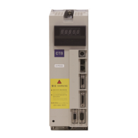
Overview of the GH DRIVER, its features, and applications in machine tools.
Steps to confirm that the materials listed on the packing list are complete and the merchandise is undamaged.
Detailed technical specifications and performance characteristics of the 3-phase 400V GH DRIVER.
Explanation of the information presented on the GH DRIVER's nameplate.
Diagrams and tables detailing the physical size and mounting requirements of the driver.
Specifies environmental conditions and spatial clearances needed for proper driver installation.
Important considerations and restrictions for using the driver, including voltage and input type.
Information on the driver's built-in protection against lightning strikes.
Guidelines for operating the driver at altitudes over 1000m due to cooling effect deterioration.
Instructions and precautions regarding the safe disposal and processing of scrapped driver components.
Guidance on choosing and connecting external devices like reactors, contactors, and filters.
Detailed diagrams and descriptions of the main circuit terminal connections for various power ratings.
Procedures and considerations for installing a residual current circuit breaker for leakage protection.
Use and precautions for the incoming line electromagnetic contactor in sequential control.
Function and connection of the AC reactor for surge suppression and power factor improvement.
Connection and precautions for external DC reactors used with 37-75KW drivers.
Selection and correct installation of noise filters to reduce high-frequency interference.
Instructions for connecting the motor to the driver's U, V, W output terminals with correct phase sequence.
Installation of filter magnetic rings near the driver to suppress common mode interference.
Using shielded cables for output lines to suppress radio and inductive interference.
Requirements and methods for proper grounding of the driver for safety and protection.
Instructions for connecting the braking resistor to the P and PB terminals.
Table providing specifications for selecting breakers, contactors, and main circuit cables.
Specifications for input/output signals, communication interfaces, and encoder connections.
Wiring diagram for the standard version control terminals, illustrating signal connections.
Detailed description of input and output signals for the GHX series driver.
Wiring diagram for the general version control terminals, illustrating signal connections.
Detailed description of input and output signals for the GHXB series driver.
Diagrams showing the pin arrangements for various connector types (T2, T3, T4, T5).
Pin definitions for rectangular connectors used with different encoder types.
Pin definitions for round connectors used with YD18K15TS/YD28K15TS encoder models.
Guidelines for connecting the 24V DC control power supply, including optocoupler isolation.
Schematic diagrams and output standards for the driver's relay output points.
Precautions for transistor output wiring, including load capacity and surge protection.
Details on connecting analog input signals (FI, FV) and power interface (FS, FC).
Defines pin assignments and types for connecting encoder interfaces T5 and T4.
Details for connecting the RS232 serial communication port (T0) for computer communication.
Information specific to manipulators used with 0.4 to 18.5kW GH DRIVER models.
Describes the appearance, functional zones, and key operations of the manipulator.
Explains the function of each key on the manipulator panel.
Details the four operating states (standby, operating, programming, fault alarm) of the driver.
Introduces the manipulator's use and basic operations, including parameter setting processes.
Provides a flowchart for modifying driver parameters using the manipulator.
Explains how to monitor driver states, interface states, and fault information.
Information specific to manipulators used with 22 to 315kW GH DRIVER models.
Describes the states and meanings of the six LED indicators on the manipulator.
Details the operating states (standby, operating, editing, fault alarm) for 22-315kW drivers.
Outlines the step-by-step process for initial power-on and testing of the driver.
Verifies correct wiring of the main circuit terminals (R, S, T) and grounding.
Confirms initial driver and motor parameters before test run, with necessary modifications.
Guidelines for conducting the test run with a load, including monitoring and adjustments.
Lists parameters for monitoring the driver's set speed, output speed, current, and voltage.
Lists parameters for monitoring encoder counts, input/output states, and temperature values.
Displays recorded fault codes and their timing for troubleshooting.
Core operational parameters including parameter level, control mode, and power code.
Parameters allowing user customization for control methods, positioning, and communication.
Parameters for fine-tuning speed and position control, rigid tapping, and swing functions.
Parameters related to bus communication settings like Modbus, EtherCAT, CAN, and Mechatrolink.
Parameters for motor control, acceleration/deceleration, and PID loop tuning.
Motor-specific parameters including rated values, inductance, and protection settings.
Parameters for configuring various encoder types, self-learning, and resolution settings.
Parameters related to positioning modes, gain settings, and swing functions.
Parameters for configuring multi-function input/output terminals and signal filtering.
Parameters for various protection functions like overvoltage, undervoltage, and encoder alarms.
System-level parameters including passwords, carrier frequency, and version information.
Configuration of speed control using analog voltage input, including terminal definitions and parameters.
Configuration of speed control using pulse input signals, including terminal definitions and parameters.
Setup for rigid tapping function using analog voltage input, including terminal definitions and parameters.
Configuration for rigid tapping and position control using pulse input signals.
Setup and parameters for achieving precise stopping positions using encoder or switch inputs.
Configuration and parameters for the swing function, including speed limits and gains.
Instructions on how to use the driver's operation panel for basic control and parameter adjustment.
Configuration parameters for establishing Modbus communication with the driver.
Details on controlling motorized spindles with Star-Delta switching for high speed and torque.
Description and parameters for configuring smooth acceleration/deceleration profiles.
Parameters for configuring different field bus types and host computer communication.
Configuration and parameters for analog voltage outputs DA1 and DA2 for monitoring or control.
Comprehensive table of error codes, possible causes, and countermeasures for driver faults.
Analysis of common operational issues without alarm codes and their troubleshooting steps.
Procedures for resetting driver alarms after fault conditions have been resolved.
Important safety warnings and general precautions before performing driver maintenance.
Guidelines for regular checks and recording of operational data to ensure optimal performance.
Recommended inspection schedule and tasks to eliminate hidden faults and ensure long-term operation.
Identification of components with limited service life (fan, capacitors) and replacement criteria.
Environmental requirements and procedures for storing the driver to prevent component degradation.
Information regarding the warranty period and conditions for driver service or repair.
Lists parameters for monitoring the driver's set speed, output speed, current, and voltage.
Lists parameters for monitoring encoder counts, input/output states, and temperature values.
Displays recorded fault codes and their timing for troubleshooting.
Core operational parameters including parameter level, control mode, and power code.
Parameters allowing user customization for control methods, positioning, and communication.
Parameters for fine-tuning speed and position control, rigid tapping, and swing functions.
Parameters for motor direction, speed ring, and position operation settings.
Motor-specific parameters including rated values, inductance, and protection settings.
Parameters for configuring various encoder types, self-learning, and resolution settings.
Parameters for various protection functions like overvoltage, undervoltage, and encoder alarms.
Parameters for configuring bus communication settings like Modbus, Ethercat, CAN, and Mechatrolink.
A comprehensive list mapping motor models to their corresponding internal codes.
| Brand | CTB |
|---|---|
| Model | BKSC-4011GHX |
| Category | Servo Drives |
| Language | English |