Do you have a question about the CTB BKSC GNX Series and is the answer not in the manual?
Overview of GH DRIVER capabilities and applications in machine tools.
Procedure for confirming product contents and checking for damage upon receipt.
Detailed technical specifications and performance characteristics of the GH DRIVER series.
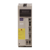
Explanation of information indicated on the driver's nameplate.
Graphical representation and measurements for physical installation.
Guidelines for selecting a suitable installation environment.
Considerations for motor characteristics and load behavior during operation.
Important usage notes and precautions related to the driver's operation.
Guidelines for the safe and environmentally responsible disposal of the driver.
Guidance on selecting and connecting external components like reactors and filters.
Detailed diagrams and descriptions for main circuit terminal connections.
Explanation of input/output signal specifications and cable requirements.
Information on connecting encoder interfaces T4 and T5.
Details on connecting the RS232 serial communication port (T0).
Describes the manipulator's appearance, keys, and functions for 0.4-18.5kw drivers.
Explains the standby, operating, programming, and fault alarm states for the driver.
Details the standby, operating, and fault alarm states of the manipulator.
Introduction to manipulator usage and parameter setting processes.
Flowchart for modifying parameters using the manipulator.
How to monitor driver states and fault information via the manipulator.
Describes the manipulator's appearance, keys, and functions for 22-315kw drivers.
Explains the driver's operating states: standby, operating, editing, and fault alarm.
Details the manipulator's states: standby, operating, and fault alarm.
Introduction to manipulator usage and parameter setting operations.
Flowchart for modifying parameters using the manipulator.
How to monitor driver states and fault information via the manipulator.
Step-by-step guide for initial driver power-on and testing procedures.
Checks for correct main circuit wiring before powering on.
Ensuring motor and driver parameters are correctly set for initial application.
Guidelines for testing the driver under load conditions.
Parameters for monitoring set speed, output speed, and current.
Parameters for monitoring encoder counts, input/output states, and temperature.
Parameters for recording and displaying fault codes and history.
Fundamental parameters for driver configuration, including control mode.
Parameters allowing users to customize driver functions and settings.
User-configurable parameters for advanced control and tuning.
Parameters for configuring bus communication settings (Modbus, EtherCAT, CAN).
User-defined parameters for motor control, acceleration, and deceleration.
Parameters related to motor specifications and electrical characteristics.
Parameters for configuring and managing encoder settings.
Parameters for setting specific functions like positioning and swing.
Parameters for configuring multi-function input/output terminals.
Parameters for setting driver protection features and alarms.
System parameters including password, version, and carrier frequency.
Details on setting speed control using analog voltage input.
Configuration for speed control using pulse input signals.
Parameters and setup for analog rigid tapping operation.
Configuration for rigid tapping and pulse position control.
Parameters and functions for achieving accurate stopping.
Parameters and functionality for swing operations.
How to use the driver's operation panel for basic control.
Configuration parameters for Modbus communication.
Control method and wiring principles for Star-Delta switching.
Parameters and descriptions for configuring S-curve acceleration/deceleration.
Parameters for integrating the driver with various field bus systems.
Configuration and application schemes for analog outputs.
Table of error codes, possible causes, and corresponding countermeasures.
Troubleshooting common issues like no display or failure to run.
Procedures for resetting driver alarms.
Important safety precautions and general maintenance reminders.
Procedures for regular checks of the driver and operating environment.
Guidelines for periodic inspections to ensure long-term performance.
Identification and inspection criteria for common wear components.
Requirements for storing the driver to prevent damage.
Information regarding the driver's warranty period and conditions.
| Brand | CTB |
|---|---|
| Model | BKSC GNX Series |
| Category | Servo Drives |
| Language | English |