Do you have a question about the CTB BKSC-4022GHX and is the answer not in the manual?
Overview of GH DRIVER, its features, and applications in machine tools.
Guidelines for checking the product upon arrival to ensure all items are present and undamaged.
Detailed technical specifications and performance characteristics of the GH DRIVER series.
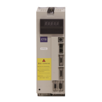
Explanation of the information indicated on the driver's nameplate.
Graphical representation and dimensions for installing the GH DRIVER series.
Environmental requirements and installation spacing for optimal driver performance and safety.
Important considerations regarding motor characteristics and load behavior during operation.
Key points to consider when applying the driver, including voltage and input limitations.
Guidelines and precautions for the safe disposal of the driver and its components.
Guidance on selecting and connecting external devices like power supplies, reactors, and motors.
Detailed diagrams and descriptions for connecting the main power circuit terminals.
Information on connecting input/output signals, communication, and encoder interfaces.
Details on connecting various types of encoders to the driver's interface ports.
Instructions for connecting the driver to a computer via the serial communication port.
Describes manipulator for 0.4-18.5kW and 22-315kW drivers.
Explains the function of each key on the manipulator panel for parameter setting and control.
Details the four operating states: standby, operating, setting/modifying, and fault alarm.
Describes the standby, operating, and fault alarm modes of the manipulator.
Introduces the use of the manipulator and basic operations for parameter setting and control.
Provides a flowchart for modifying parameters using the manipulator's interface.
Explains how to monitor driver status, interface, and fault information via the manipulator.
Step-by-step guide for initial power-on and testing of the driver.
Checks for correct wiring of the main circuit, including power supply and motor connections.
Ensures that motor and driver parameters are correctly set for initial application.
Guidelines for performing tests with a load applied to the motor.
Parameters for monitoring set speed, output speed, and driver output current.
Parameters related to encoder counting, input/output states, and driver temperatures.
Parameters for recording and displaying fault codes and histories.
Fundamental parameters for selecting control mode, command mode, and motor identification.
Parameters allowing users to define custom functions for positioning and I/O.
Parameters for fine-tuning speed and position control loops, including rigid tapping.
Parameters for configuring bus communication settings like Modbus and EtherCAT.
User-configurable parameters for motor control, including current and speed loops.
Parameters specifying motor characteristics such as current, voltage, power, and inductance.
Parameters for configuring encoder types, resolution, and self-learning functions.
Parameters related to positioning functions, including gain, speed, and timing.
Parameters for configuring multi-function input/output terminals and filter settings.
Parameters for setting various protection functions like overvoltage and stall alarms.
System parameters including password, carrier frequency, and software versions.
Details terminal definitions and parameters for controlling speed via analog voltage.
Explains terminal definitions and parameters for speed control using pulse signals.
Covers terminal definitions and parameters for rigid tapping using analog voltage.
Details terminal definitions and parameters for rigid tapping/positioning via pulse signals.
Describes terminal definitions and parameters for achieving accurate stopping positions.
Covers port definitions and parameters related to swing motion control.
Instructions for operating the driver using the control panel for testing purposes.
Parameters and principles for establishing Modbus communication.
Explains the need for and control method of star-delta switching for motor operation.
Describes the S-curve acceleration/deceleration profile and related parameters.
Parameter settings for different fieldbus types and host computer integration.
Details parameters and application schemes for analog voltage outputs DA1 and DA2.
A table detailing error codes, possible causes, and countermeasures for driver faults.
Analysis of common operational issues not indicated by alarm codes.
Procedures for resetting driver alarms after fault resolution.
Important safety precautions and general guidance before performing maintenance.
Scheduled checks and recording of operational data for ongoing driver health.
Periodic inspections to ensure long-term, high-performance operation and eliminate hidden faults.
Identification and inspection of common wearing components like fans and capacitors.
Guidelines for proper storage environment to maintain driver integrity.
Information regarding the warranty period and conditions for the driver.
| Brand | CTB |
|---|---|
| Model | BKSC-4022GHX |
| Category | Servo Drives |
| Language | English |