10 se c t i O n 4— as s e M b l y & se t -up
Install the frame mounting bracket (1, Fig.3-2) onto each 3.
side of the tractor frame.
Series 2000 & 2500 Tractors Before Mfg. Date a.
J315. Looking beneath the front of both running
boards, locate the forward most open hole in each
side of the tractor frame. Refer to Figure 4-10.
Series 2500 Tractors Mfg. Date K015 and After. b.
Looking beneath the front of both running boards,
locate the forward most open hole in each side of
the tractor frame. See Figure 4-11.
Tractor Preparation
This section describes the steps necessary to prepare the
appropriate tractor models for installation of the snow thrower
attachment. Some instructions apply only to specific production
model years. The production models referred to will be noted in
the heading for those instructions. Skip all instructions that do
not apply to your installation.
WARNING! If the tractor has been recently
operated, the muffler, exhaust pipe, and
surrounding areas will be HOT. Allow the tractor to
cool before beginning preparation.
NOTE: The mower deck and its front lift rod, or any other front
mounted attachment must be removed from the tractor.
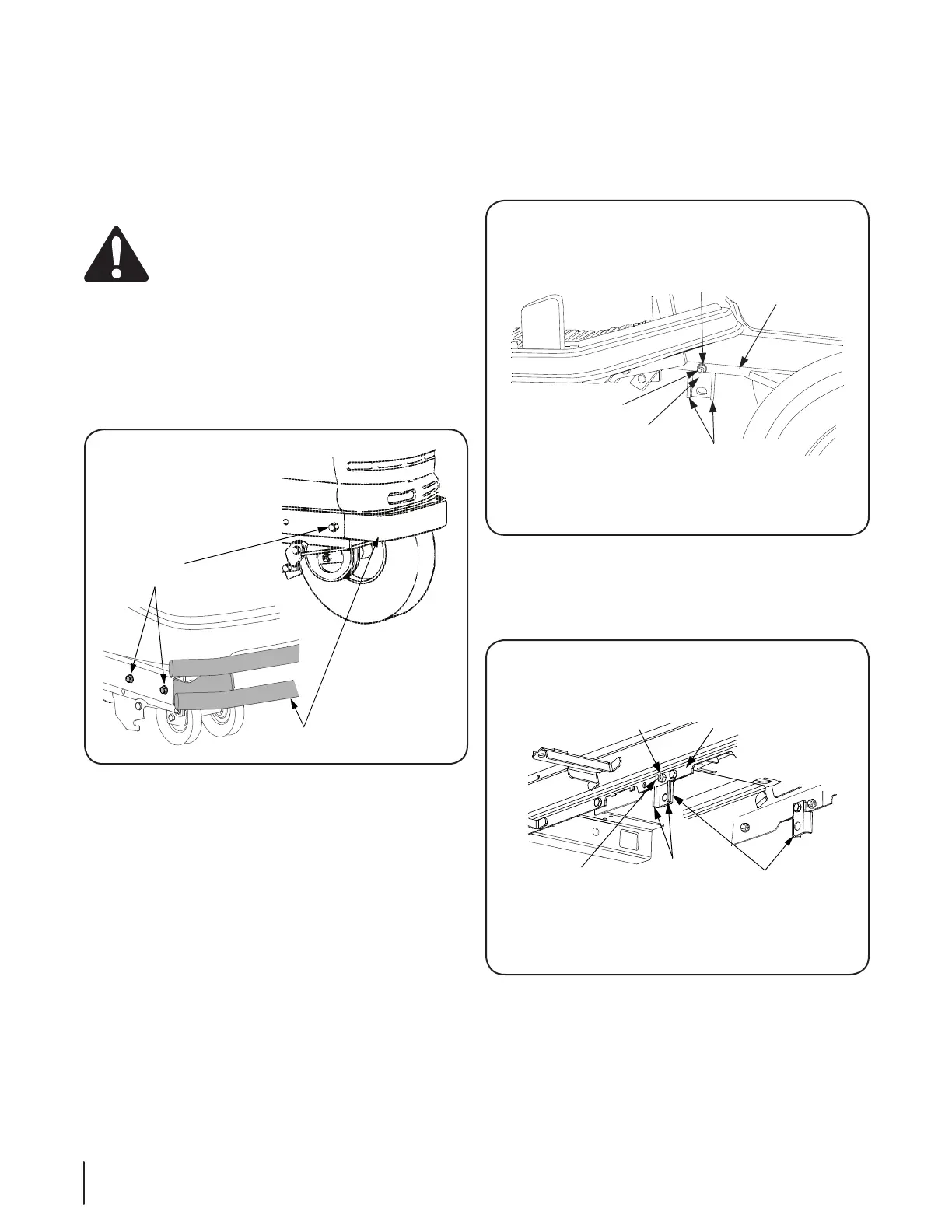
Remove the front bumper from the tractor frame by 1.
removing the hex tap screws securing the bumper in each
side of the tractor frame. Slide the bumper out of frame.
Store screws and bumper for later reassembly when the
snow thrower is removed. Refer to Figure 4-9.
Check for the presence of red reflector labels on the rear 2.
fender. If none are present, install the two reflector labels
provided with the snow thrower attachment. Thoroughly
clean the rear fender. Remove the backing from the
adhesive side of one reflector label. Position the label
horizontally and carefully affix to one side of the rear
fender of the tractor. Install the other reflector label to the
other side of the fender.
HEX TAP
SCREWS
FRONT BUMPER
TRACTOR
FRAME
HEX FLANGE
LOCK NUT
HEX CAP
SCREW
FRAME
MOUNTING
BRACKET
SIDE
FLANGES
TRACTOR
FRAME
HEX FLANGE
LOCK NUT
HEX CAP
SCREW
FRAME
MOUNTING
BRACKET
SIDE
FLANGES
Figure 4-9
Figure 4-10
Figure 4-11
 Loading...