Adjustments & Operation
6
15
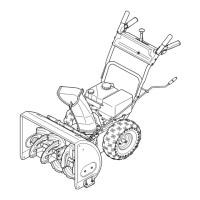
Turn the drift cutters to the up position and secure b.
with the carriage bolts and hex insert lock nuts as
shown in Figure 6-2.
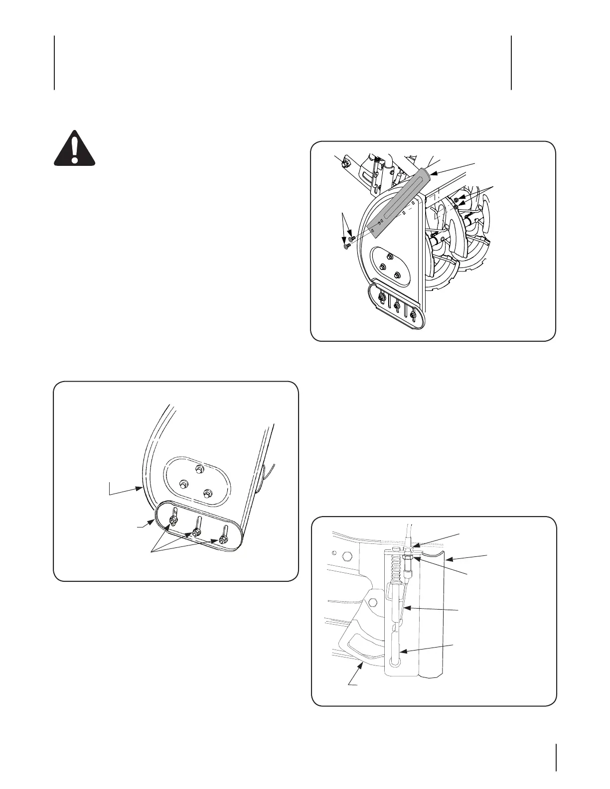
Lift Latch Adjustment.
The lift index rod is operated by the trigger assembly on the lift
handle, through the latch release cable. The cable is adjustable to
assure proper engagement and release.
If the index rod does not latch securely, loosen the a.
upper jam nut and tighten the lower jam nut until
the rod fully seats in the latch slot of the lift latch
bracket. Refer to Figure 6-3.
If the release cable has excess slack and it is difficult b.
to disengage the rod from the latch slot, loosen the
lower jam nut and tighten the upper jam nut until
the excess slack is removed from the cable. Refer to
Figure 6-3.
Adjustments
WARNING! If the snow thrower is to be used on
gravel surfaces, use extreme caution to avoid
picking up gravel with the shave plate or auger.
Loose gravel can damage the auger or housing, and
could be thrown at high speed by the impeller —
causing possible injury to bystanders or damage to
surrounding objects.
Skid Shoe Adjustment
The skid shoes are mounted on each side of the auger housing.
They determine the distance the shave plate is raised above the
plowing surface. The shave plate should be high for a gravel
driveway or other uneven surfaces and low for paved surfaces.
Adjust the skid shoes as follows:
Raise the snow thrower assembly slightly off the a.
ground and place a spacer under each end of the
shave plate.
Loosen the hex nuts and bell washers securing the b.
skid shoes to the housing. Refer to Figure 6-1.
Move the skid shoes up or down to the desired c.
position and securely tighten the hex nuts. Adjust
both skid shoes to the same height.
Drift Cutters
Drift cutters on both sides of the auger housing can be adjusted
to the up position for a higher cut. Refer to Figure 6-2 and
proceed as follows:
Remove each drift cutter by removing the two hex a.
insert lock nuts and carriage bolts.
AUGER
HOUSING
SKID SHOE
HEX NUTS AND
BELL WASHERS
CARRIAGE
BOLT
DRIFT
CUTTER
HEX INSERT
LOCK NUT
UPPER JAM NUT
LIFT LATCH
BRACKET
LOWER JAM NUT
RELEASE CABLE
LIFT INDEX ROD
LIFT
BRACKET
Figure 6-1
Figure 6-2
Figure 6-3
 Loading...