Installation & Removal
5
12
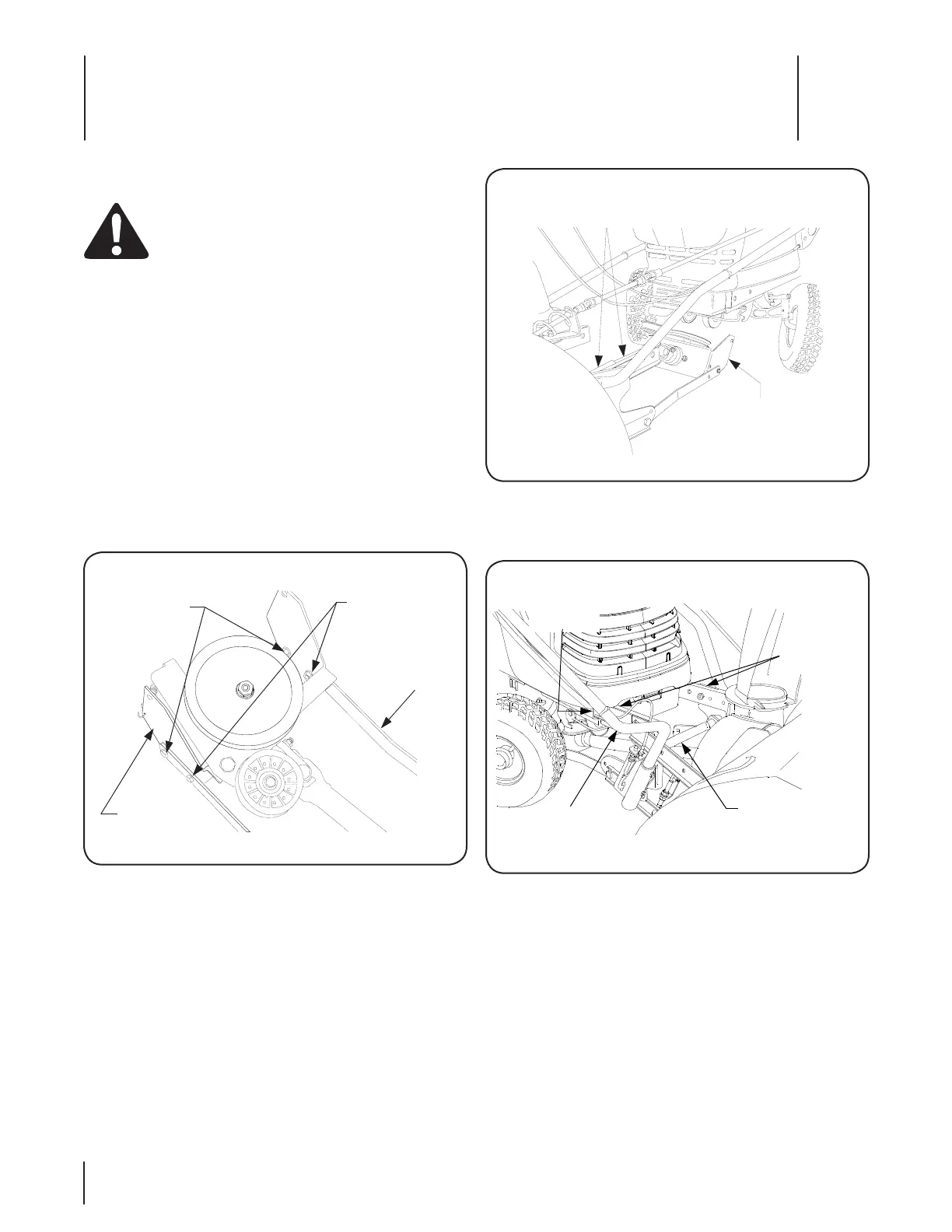
Slide the snow thrower assembly rearward until the 4.
channel brackets of the hitch assembly engage the frame
channels of the tractor. See Figure 5-3.
Snow Thrower Installation
WARNING! Before installing the snow thrower
assembly onto the tractor, ensure the PTO switch
and ignition switch are in the OFF position, the
parking brake is locked, and that the exhaust system
and surrounding areas have adequately cooled.
NOTE: To ease insertion into the tractor frame channels, apply
a light coating of grease to the channel brackets of the snow
thrower hitch assembly ( Refer to Figure 5-3).
Position the snow thrower assembly directly in front of the 1.
tractor with the subframe assembly extending rearward.
NOTE: Because of lower ground clearance on tractors
equipped with 15” front tires and 20” rear tires, the gearbox
mounting bracket, as assembled on the snow thrower
subframe, may not clear the front axle of the tractor. Note
that steps 2, 3 and 6 apply only to these tractors.
Units with 15” front tires ONLY. Remove the front hex flange 2.
lock nuts and cap screws securing the gearbox mounting
bracket to the subframe arms. Loosen the rear fasteners.
See Figure 5-1.
Units with 15” front tires ONLY. Using care to avoid 3.
separating the rear half of the drive shaft from the front
half, tilt the gearbox mounting bracket rearward. See
Figure 5-2.
NOTE: Turning the tractor’s front tires fully to the left or
right will slightly raise the front axle of the tractor and
provide more ground clearance.
SUBFRAME
ARM
REMOVE
FRONT
FASTENERS
LOOSEN
REAR
FASTENERS
GEARBOX
MOUNTING
BRACKET
GEARBOX MTG.
BRACKET TILTED
REARWARD
DRIVE SHAFT
HALVES
CHANNEL
BRACKETS
FRONT LIFT
SHAFT
LIFT HANDLE
FRAME
CHANNEL
Figure 5-1
Figure 5-2
Figure 5-3
 Loading...