C,
washers. Remove the lock nuts, shoulder
screws, and bell washers fastening the front
ball wheels to the deck gauge wheel brackets.
Again place the tractor implement lift handle in
the normally desired mowing height setting.
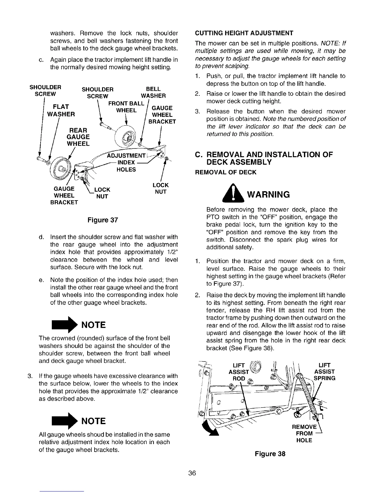
SHOULDER SHOULDER BELL
SCREW SCREW WASHER
F, ._ \ FRONT BALL /
L_! \ WHEEL / GAUGE
WASHER \ --_-- / WHEEL
/ REAR _ _ _RACKET
WHEEL NUT
BRACKET
,
Figure 37
d,
e,
Insert the shoulder screw and flat washer with
the rear gauge wheel into the adjustment
index hole that provides approximately 1/2"
clearance between the wheel and level
surface. Secure with the lock nut.
Note the position of the index hole used; then
install the other rear gauge wheel and the front
ball wheels into the corresponding index hole
of the other guage wheel brackets.
I NOTE
The crowned (rounded) surface of the front bell
washers should be against the shoulder of the
shoulder screw, between the front ball wheel
and deck gauge wheel bracket.
If the gauge wheels have excessive clearance with
the surface below, lower the wheels to the index
hole that provides the approximate 1/2" clearance
as described above.
I NOTE
All gauge wheels shoud be installed in the same
relative adjustment index hole location in each
of the gauge wheel brackets.
CUTTING HEIGHT ADJUSTMENT
The mower can be set in multiple positions. NOTE: If
multiple settings are used while mowing, it may be
necessary to adjust the gauge wheels for each setting
to prevent scalping.
1. Push, or pull, the tractor implement lift handle to
depress the button on top of the lift handle.
2. Raise or lower the lift handle to obtain the desired
mower deck cutting height.
3. Release the button when the desired mower
position is obtained. Note the numbered position of
the lift lever indicator so that the deck can be
returned to this position.
C. REMOVAL AND INSTALLATION OF
DECK ASSEMBLY
REMOVAL OF DECK
1,
2,
WARNING
Before removing the mower deck, place the
PTO switch in the "OFF" position, engage the
brake pedal lock, turn the ignition key to the
"OFF" position and remove the key from the
switch. Disconnect the spark plug wires for
additional safety.
Position the tractor and mower deck on a firm,
level surface. Raise the gauge wheels to their
highest setting in the gauge wheel brackets (Refer
to Figure 37).
Raise the deck by moving the implement lift handle
to its highest setting. From beneath the right rear
fender, release the RH lift assist rod from the
tractor frame by pushing down then outward on the
rear end of the rod. Allow the lift assist rod to raise
upward and disengage the lower hook of the lift
assist spring from the hole in the right rear deck
bracket (See Figure 38).
LIFT LIFT
ASSIS'I ASSIST
SPRING
FROM
HOLE
Figure 38
36
 Loading...