If also replacing the drive belt, proceed to the “Drive Belt”
instruction. If not, reassemble by performing the previous
steps in the opposite order and manner of removal.
NOTE: Make sure to remove the piece of wood blocking the
impeller.
Proper Adjustment: With the auger clutch lever in the
disengaged position, the top surface of the new belt
should be even with the outside diameter of the pulley.
To adjust, disconnect ferrule from brake bracket 10.
assembly and thread ferrule in (towards idler) to
increase tension on belt, and out to decrease tension.
See Figure 7-4.
NOTE: The brake puck must always be firmly seated in the
pulley groove when auger control is disengaged.
IMPORTANT: Repeat the “Auger Drive Control Test” from the
Assembly section before operating snowthrower.
Drive Belt
If not already done, remove auger belt as previous 1.
instructed.
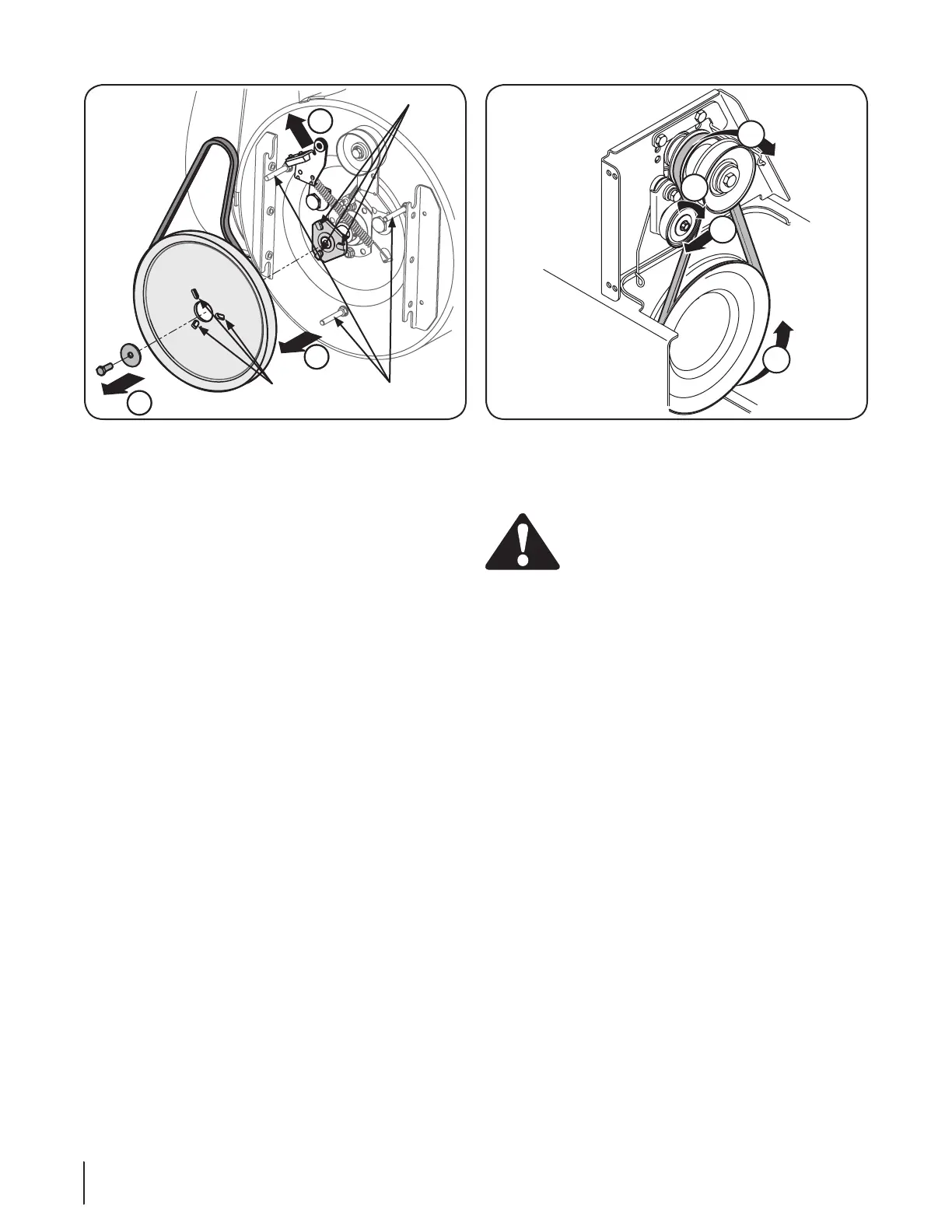
a. Pull the idler pulley away from the backside of
the drive belt to relieve the tension.
b. Slide the drive belt off the idler pulley. See Figure
7-9. Carefully release the idler pulley.
Remove the belt from the bottom drive pulley. 2.
Remove the belt from the engine pulley.3.
Install the new belt on the pulleys in the reverse order 4.
and re-tension with the idler pulley.
Reassemble your unit by performing the previous steps 5.
in the opposite order.
Changing Friction Wheel
WARNING: Run the engine completely dry of
gasoline before tipping snowthrower.
Tip the snowthrower up and forward, so that it rests on •
the housing.
Remove screws from the frame cover underneath the •
snowthrower. See Figure 6-6.
Remove the right wheel(s) from the axle. See Figure •
7-10.
Using a 3/4” wrench, hold the hex shaft and remove •
the hex bolts and cupped washer and bearing from left
side of the frame. Refer to Figure 7-10.
Holding the friction wheel assembly, slide the hex shaft •
out of the right side of the unit. The spacer on the left
side of the hex shaft will fall and the sprocket should
remain hanging lose in the chain. See Figure 7-11.
Lift the friction wheel assembly out between the axle •
shaft and the drive shaft assemblies.
Remove four screws securing the friction wheel rubber •
between the friction wheel plates. See Figure 7-12.
Discard old rubber.
Reassemble the new friction wheel rubber to the •
friction wheel assembly, tightening the four screws in
rotation to 6-9 ft. lbs. It is important to assemble the
rubber on the friction wheel symmetrically for proper
functioning.
Insert the pin from the shift arm assembly into the •
friction wheel assembly and hold assembly in position.
Refer to Figure 7-13 .
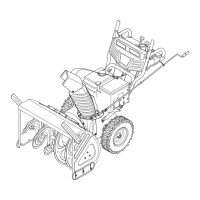
Figure 7-9
Figure 7-8
A
C
B
Adapter Post
Belt Keeper
Pulley Slot
20 Se c t i o N 7— Se r v i c e
 Loading...