15
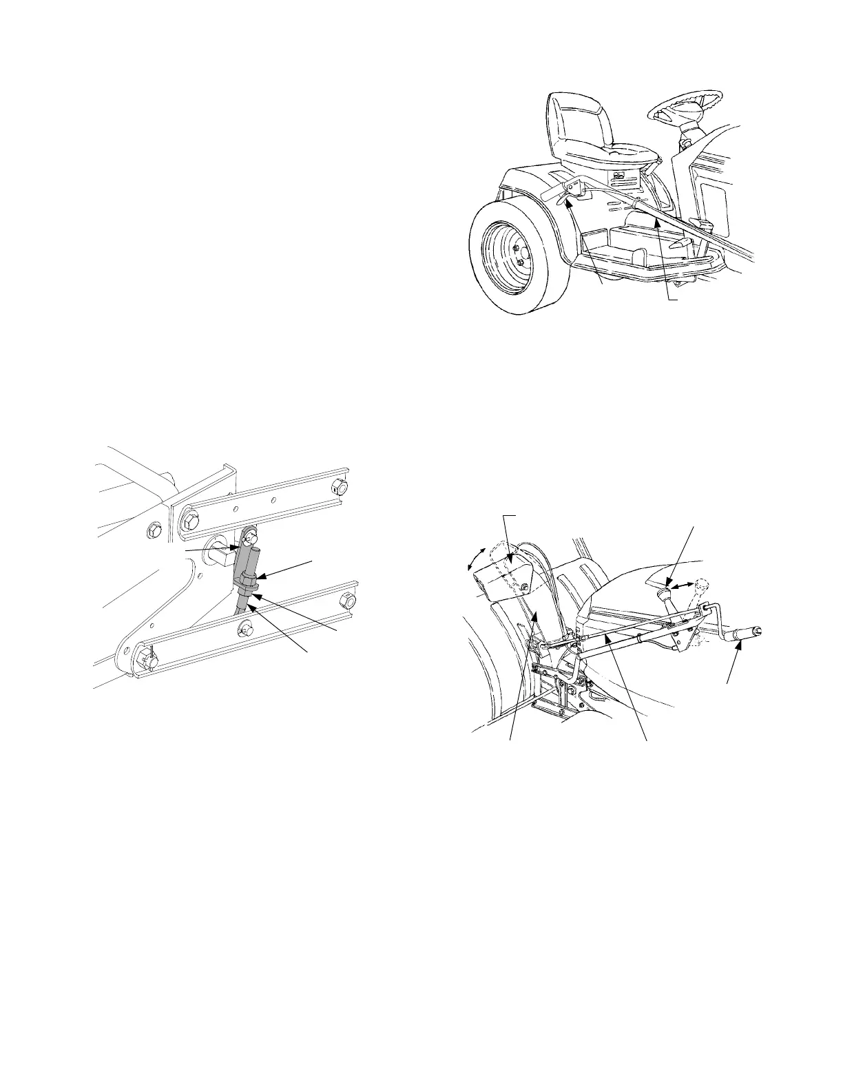
4. Lift Link Adjustment
The adjustable lift link assemblies at each end of
the lift shaft are adjusted at the factory and should
not require readjustment. However if the drive
shaft makes contact with any part of the tractor
when the snow thrower is raised to the transport
position, the lift links should be adjusted as follows:
a. Raise the snow thrower to its fully raised posi-
tion.
b. Loosen the hex insert lock nut at the top of one
adjustable eyebolt link. Refer to Figure 27.
c. Thread the hex nut beneath the lift link up the
eyebolt to lengthen the lift link assembly.
Lengthen the lift link assembly only as needed
to eliminate the drive shaft contact. Retighten
the hex insert lock nut after adjusing. See Fig-
ure 27.
d. Repeat the above procedures to adjust the lift
link assembly on the other side of the snow
thrower to the same length.
Figure 27
B. CONTROLS.
1. The snow thrower controls are conveniently
located at the operator’s position on the tractor.
2. The lift handle is used to raise and lower the snow
thrower. To raise the snow thrower, pull back and
down on the lift handle until the lift index rod fully
engages the latch slot of the lift latch bracket. To
lower the snow thrower, push slightly downward
on the lift handle, then pull the trigger. With the
trigger pulled, lower the snow thrower slowly until
it contacts the ground. Refer to Figure 28.
Figure 28
3. The discharge chute control crank is located on
the left hand side of the snow thrower. The chute
crank controls the direction in which snow is
thrown. The discharge radius is 190 degrees. Turn
the crank clockwise to discharge to the left and
counterclockwise to discharge to the right. See
Figure 29.
Figure 29
4. The chute tilt handle is also located on the left
hand side of the snow thrower. The pivoting upper
section of the discharge chute pivots downward
when the tilt handle is pushed forward —
decreasing the distance snow is thrown. Pulling
the handle backwards pivots the upper section
upward — increasing the distance snow is thrown.
Refer to Figure 29.
Lift Handle & Bracket Removed For Clarity
HEX NUT
HEX INSERT
LOCK NUT
LIFT EYE
BOLT
LIFT LINK
TRIGGER
ASSEMBLY
LIFT HANDLE
DISCHARGE CHUTE
UPPER SECTION
CHUTE
TILT HANDLE
CHUTE
CRANK
HANDLE
CHUTE CRANK ROD
DISCHARGE
CHUTE
 Loading...