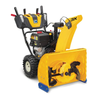
8
SECTION II. ASSEMBLY
A. SNOW THROWER ASSEMBLY PREPARATION.
WARNING: Before beginning preparation
of the snow thrower assembly, select a
firm and level surface that is large enough
to accommodate both the snow thrower
attachment and tractor. Engage the
tractor parking brake.
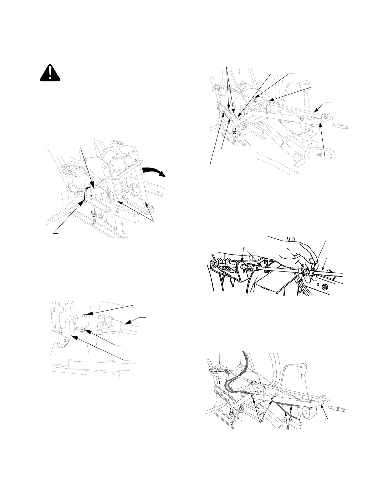
1. Cut the cable tie(s) securing the drive shaft to the
snow thrower subframe and carefully unfold the
subframe arms (See Figure 3).
Figure 3
2. Slide the front end of the drive shaft onto the input
shaft of the sprocket box assembly on the rear of
the snow thrower. Align the holes and secure with
hex cap screw (10, Fig.2) and hex insert lock nut
(16, Fig.2). See Figure 4.
Figure 4
3. Install the chute crank support tube (B, Fig.1) onto
the LH upper link of the snow thrower (A, Fig.1)
subframe using the hex cap screw (7, Fig.2), hex
cap screw (17, Fig.2) and two hex flange lock nuts
(13, Fig.2). Note: the longer hex cap screw (17)
must be installed in the rearward hole. Refer to
Figure 5.
Figure 5
4. After making sure the chute crank rod is routed
through the eyebolt, insert the rod into the sleeve
of the joint block on the chute crank assembly.
Align the holes and secure the rod with the cotter
pin (4, Fig.2). See Figures 5 and 6.
Figure 6
5. Route the tilt handle cables along the inside of the
upper chute crank support tube and secure to the
support tube with two cable ties (11, Fig.2). See
Figure 7. Cut excess length from the cable ties.
Figure 7
CABLE TIE
SUBFRAME
ARMS
DRIVE
SHAFT
DRIVE SHAFT
HEX CAP
SCREW
HEX INSERT
LOCK NUT
SPROCKET BOX
CHUTE
CRANK
ROD
JOINT BLOCK
CRANK ROD
EYEBOLT
CHUTE CRANK
SUPPORT TUBE
HEX CAP SCREW
(1-1/2" LG.)
HEX CAP SCREW
(1-1/4" LG.)
LH UPPER
LINK
HEX FLANGE
INSERT LOCK NUT
COTTER PIN
JOINT
BLOCK
CHUTE CRANK
ASSEMBLY
CHUTE
CRANK
ROD
CABLE TIE
TILT HANDLE
CABLES
CHUTE CRANK
SUPPORT TUBE
 Loading...