9
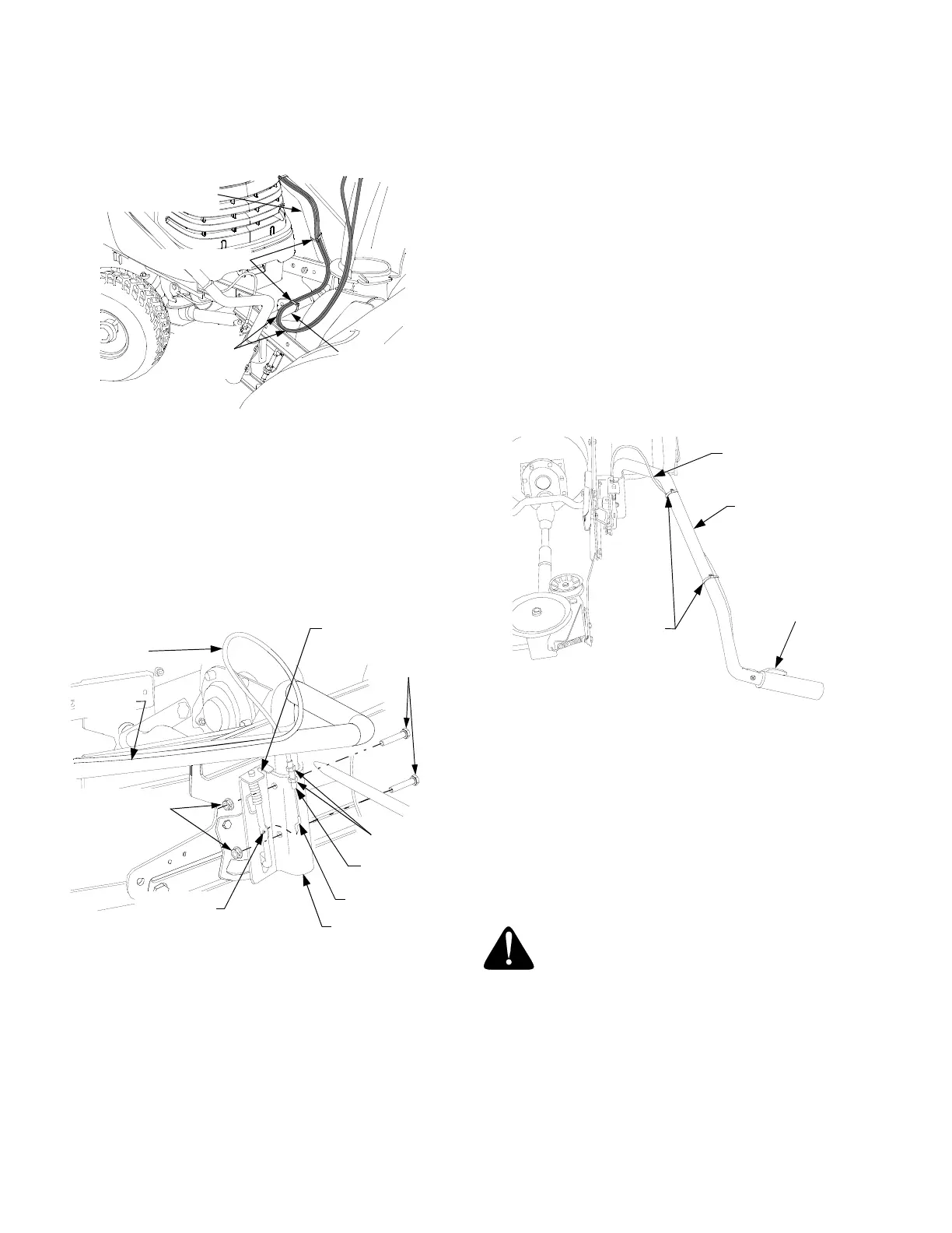
6. Route the tilt handle cables along the bend in the
lower end of the chute crank support tube and
secure to the support tube with a cable tie (11).
See Figure 8.
Figure 8
7. Route the tilt handle cables across the top of the
snow thrower lift shaft toward the right side of the
snow thrower. Loosely fasten the cables to the lift
shaft with a cable tie (11). Do not fully tighten the
cable tie. Refer to Figure 8.
8. Insert the lower end of the lift handle assembly (C,
Fig.1) into the lift bracket located on the right side
of the snow thrower subframe. See Figure 9.
Figure 9
NOTE: The latch release cable may, or may not, have
been connected to the lift index rod at the factory. If
already connected, skip to Step 12. If not connected,
perform the following steps 9-11 to connect the cable.
9. Insert the bottom of the cable ‘Z’ end fitting through
the hole in the lift index rod. Refer to Figure 9.
10. If necessary, turn the jam nuts on the conduit fitting
to create a space between the nuts. With a jam nut
positioned both above and below the lift bracket,
slide the conduit fitting fully into the slot of the lift
bracket. Refer to Figure 9.
11. Temporarily tighten the jam nuts against the upper
and lower surfaces of the lift bracket.
12. Align the holes of the lift handle and lift bracket,
and secure with the two hex cap screws (6, Fig.2)
and hex flange lock nuts (13, Fig.2). Refer to
Figure 9.
13. Refer to Lift Latch Adjustment on Page 14 for
instructions to adjust the cable.
14. Route the latch release cable along the lift handle
and secure the cable to the handle using two tie
straps (11, Fig.2) as shown in Figure 10. Cut the
excess from the tie strap ends.
Figure 10
B. TRACTOR PREPARATION.
This section describes the steps necessary to pre-
pare the appropriate tractor models for installation of
the snow thrower attachment. Some instructions ap-
ply only to specific production model years. The pro-
duction models referred to will be noted in the
heading for those instructions. Skip all instructions
that do not apply to your installation.
WARNING: If the tractor has been
recently operated, the muffler, exhaust
pipe, and surrounding areas will be HOT.
Allow the tractor to cool before begin-
ning preparation.
NOTE: The mower deck and its front lift rod, or any
other front mounted attachment must be removed from
the tractor.
CABLE TIES
TILT
HANDLE
CABLES
CHUTE CRANK
SUPPORT TUBE
LIFT SHAFT
LATCH
RELEASE
CABLE
LIFT BRKT.
SLOT
HEX CAP
SCREW
LIFT INDEX
ROD HOLE
CABLE ‘Z’
END FITTING
CONDUIT
FITTING
LIFT BRACKET
HEX FLANGE
LOCK NUT
LIFT
HANDLE
JAM NUT
LATCH
RELEASE
CABLE
TRIGGER
ASSEMBLY
LIFT HANDLE
CABLE
TIE
 Loading...