Chassis
5‐8
5.
Inspect the Tie Rods
Look for bends or damage.
6.
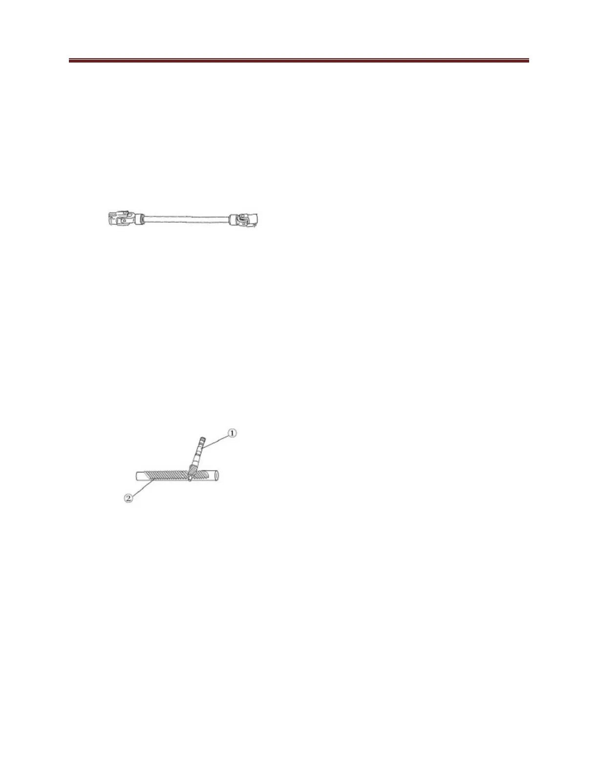
Inspect the steering Joint
Look for cracks or distortion.
7.
Inspect the rack and pinion gear
Check the splines on the
end of the shaft for wear or
damage.
Check the gear teeth of the
pinion shaft and mating
surface of the rack for wear
or damage.
Measure backlash of the
rack and pinion.
Installation
1.
Install the rack and pinion assembly
to the frame.
Bolt M10×30
48 Nm (4.8m · kg, 35 ft · lb)
Nut M10
40 Nm (4.0m · kg, 29 ft · lb)
2.
Connect the steering joint
Bolt M8×20
32 Nm (3.2m · kg, 23 ft · lb)
3.
Attach the steering tube to the
frame.
Bolt M8×20
32 Nm (3.2m · kg, 23 ft · lb)
4.
Attach the steering wheel and cover
Steering wheel nut torque
48 Nm (4.8m · kg, 35 ft · lb
The Brake System
The brake system is crucial to the life
of
the operator and passengers and
therefore
must be periodically inspected
and
maintained.
This vehicle uses the double return route
hydraulic pressure disc brake system.
Please follow the tips of inspection below.
1.
Check the brake fluid level in the
brake reservoir. If it is low add the
correct amount of manufacturer
recommended brake fluid to ensure
the level is above the minimum
mark.
2.
3.
Check the brake pedal height.
It should be set between 20 and
30mm. If out of spec, adjust it to
m
eet
the required travel distance.
Check for spongy feel of the pedal. If
it
feels soft, a brake fluid change is
necessary or the system needs to be
bled of air. When bleeding be sure to
keep the reservoir full so not to allow
more air into the system.
Must use DOT3 brake fluid.
 Loading...