Section 6 — Maintenance & adjuStMentS
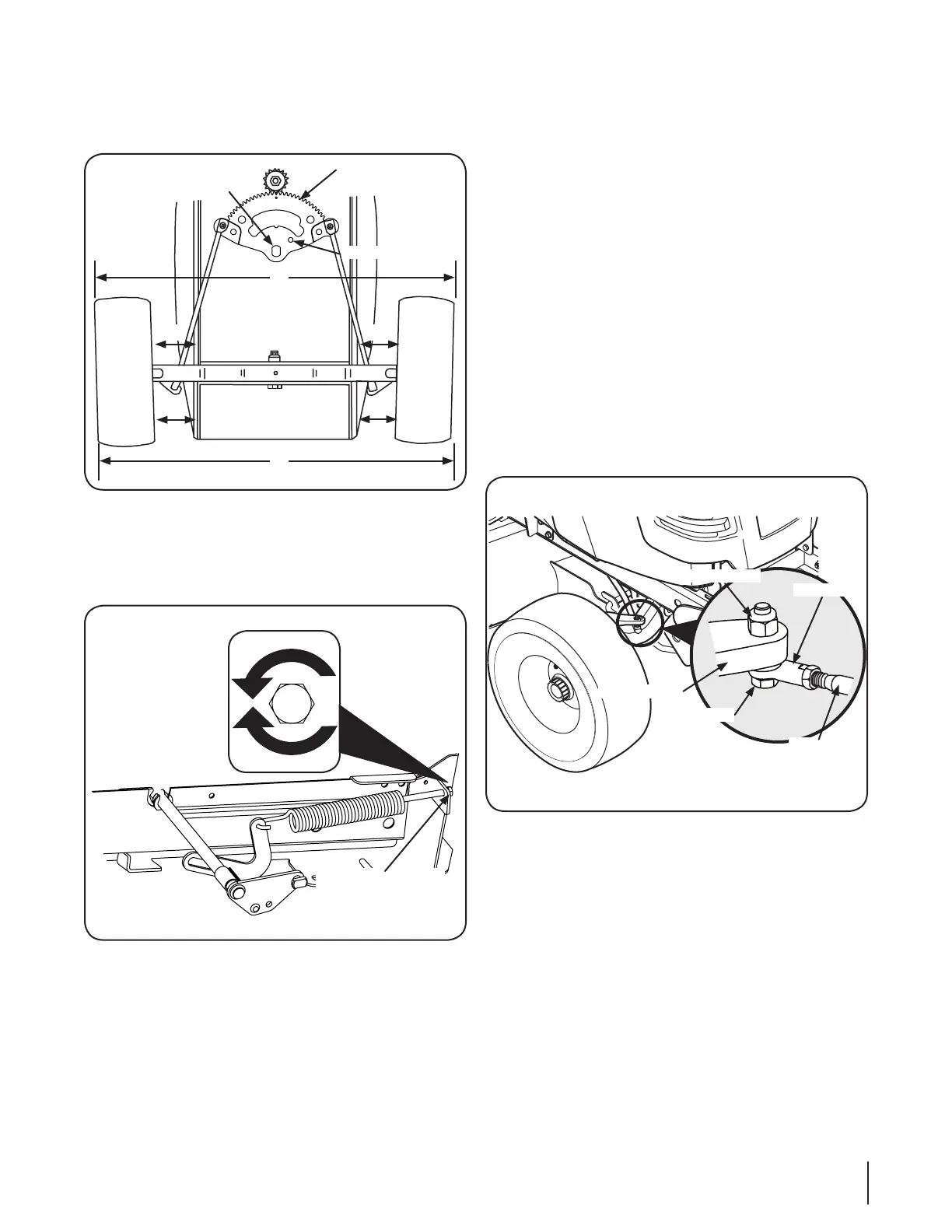
Wheel Alignment
The front wheels should toe-in approximately ⁄ to ⁄, as
measured across dimensions A and B. See Figure 6-9.
Centering Hole
Steering Gear
Centered
A
B
C C
D
D
Pivot Hole
Figure 6-9
Lift Handle Adjustment (If so equipped)
The effort required to operate the implement lift handle can be
varied by loosening or tightening the lift assist spring adjusting
Decrease effort
Increase effort
Figure 6-10
NOTE: The deck and/or attachment should be installed
before making adjustments to this spring.
Place the deck/attachment into the lowest position for making
adjustments. This ensures that the spring is extended the furthest.
The bolt can be accessed from the rear of the tractor, inside the left
rear wheel. Turning adjusting bolt clockwise will decrease the manual
effort required for lifting attachments; turning counterclockwise will
increase the effort needed to lift the attachment.
NOTE:
float and/or fail out of the notches. There should always be a
downward/forward bias on the lever for proper operation.
Steering/Toe-in Adjustment
To adjust front wheel toe-in, proceed as follows:
Check the steering gear to ensure it is in the centered
position. The hole in the steering segment gear will align
with the hole in the steering housing (See Figure 6-9).
NOTE: A ⁄
assure the steering segment is centered.
2. Mark the front horizontal diameter of both front wheels at
the same spot on each wheel-preferably the inner bead
flange of the wheel rims. Mark the rear horizontal diameter
of both front wheels in the same manner.
Measure the distance between the bottom edges of the
tractor frame channels and the marks on the front of each
wheel (See measurement D in Figure 6-9). These two
measurements should be equal.
4. Measure the distance between the frame and the marks on
the rear of each front wheel (See measurement C in Figure
6-9). Measurement D should be approximately ⁄- to ⁄-
inch less than measurement C on each side of the tractor.
5.
Ball Joint
Drag Link
Hex Lock Nut
Jam Nut
Steering Arm
Figure 6-11
6. Disconnect the front ball joints from the steering arms by
move each wheel to achieve the required toe-in and equal
D measurements.
7. Making sure not to move the steering gear or either wheel,
turn the ball joint in or out on each drag linkas necessary to
align with the hole in each steering arm.
8. Reinstall the ball joints in the steering arms and secure with
the hex lock nuts. Tighten the jam nuts against the ball joints.
23
 Loading...