36
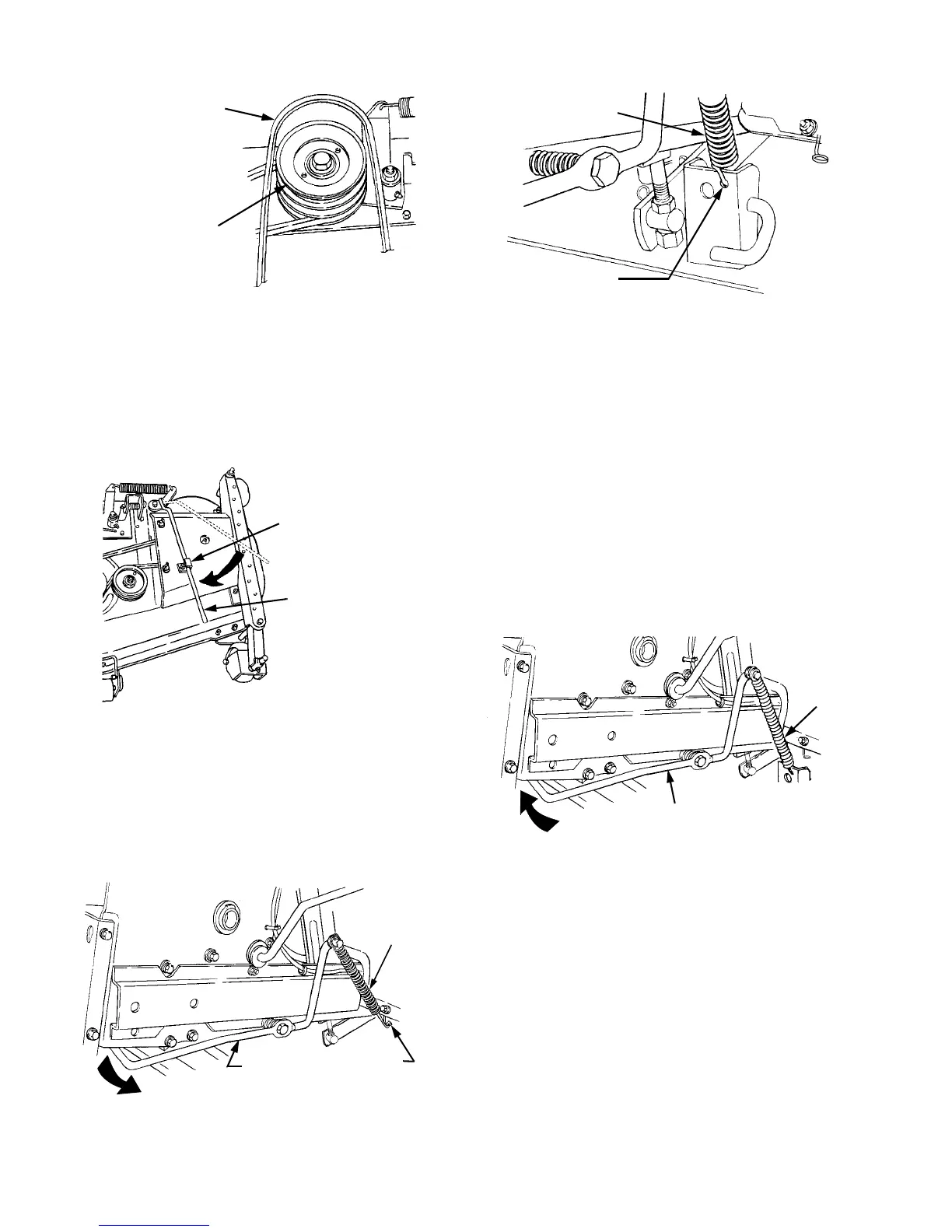
Figure 44
17. While holding the belt in position, rotate the deck
idler arm lever into its stop bracket to tension the
PTO belt (Refer to Figure 45). Make certain the
PTO belt is properly positioned in the PTO clutch
pulley and both lower front pulleys. Reposition if
necessary.
Figure 45
18. Raise the deck by moving the implement lift handle
to its highest setting.
19. From beneath the right rear fender, push the lift
assist rod down and outward to release from the
frame. Disengage the hook of the lift assist spring
from the pigtail hook (See Figure 46).
Figure 46
Figure 47
20. Install the lower hook of the lift assist spring into
the hole in the right rear deck bracket (See Figure
47).
21. Tension the lift assist spring by pushing downward
and then inward on the rear of the lift assist rod so
that the flange at the rearward end of the rod locks
inside the tractor frame (See Figure 48).
Figure 48
22. From beneath the left rear fender, repeat the
procedures described in steps 19 through 21 to
release, install and tension the left hand lift assist
rod and spring.
23. Connect the spark plug wires if previously
disconnected.
MOWER DECK
CENTER DOUBLE
PULLEY
PTO BELT
FRONT OF DECK
IDLER ARM
LEVER
STOP BRACKET
PIGTAIL
HOOK
LIFT ASSIST
ROD
LIFT
ASSIST
SPRING
LIFT ASSIST
SPRING
HOLE IN REAR
BRACKETDECK
LIFT ASSIST
ROD
LIFT
ASSIST
SPRING

 Loading...