21
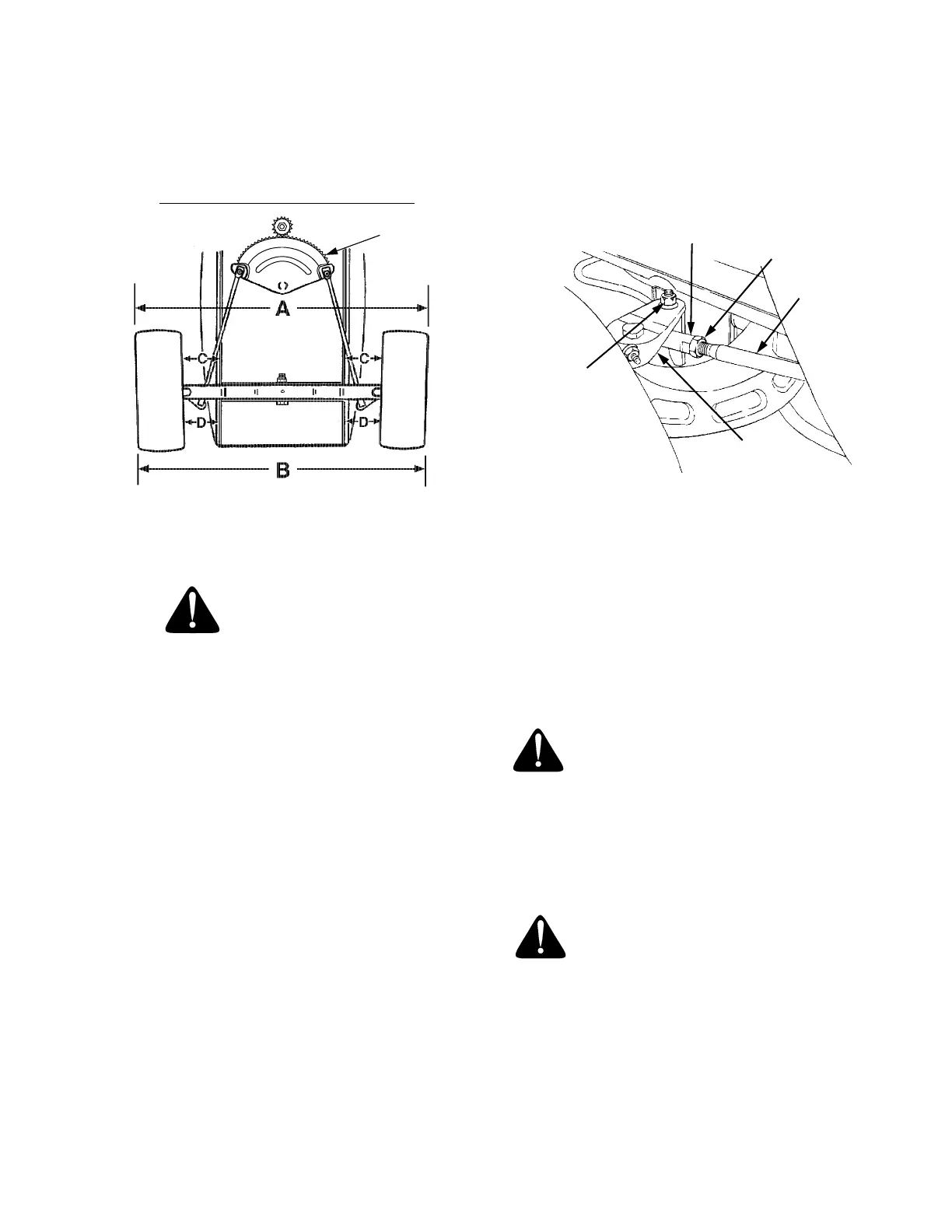
WHEEL ALIGNMENT
The front wheels should toe-in approximately 1/8 to
1/4 inch, as measured across dimensions A and B
shown in Figure 14.
Figure 14
FRONT WHEEL ADJUSTMENT
WARNING
Place the tractor on a firm and level surface.
To adjust the toe-in, proceed as follows:
1. Check the steering gear to ensure it is in the cen-
tered position (See Figure 14).
2. Place a mark at the same spot on both front
wheels; preferably the inner bead flange of the
wheel rims.
3. Rotate the wheels to position the marks at the front
horizontal diameter of the wheels, then measure
the distance between the marks and the bottom
edges of the tractor frame channels (See
measurement D in Figure 14). These two
measurements should be equal.
4. While holding the steering gear to prevent the
steering knuckles from moving, rotate the marks to
the rear horizontal diameter. Measure the distance
between the marks and the frame (See
measurement C in Figure 14). Measurement D
should be approximately 1/16 to 1/8 inch less than
measurement C on each side of the tractor.
5. Disconnect the front ball joints from the steering
arms by removing the hex lock nuts (Refer to
Figure 15). Manually move each wheel to achieve
the required toe-in and equal D measurements.
6. Loosen the jam nuts from the ball joints (See
Figure 15).
Figure 15
7. Making sure not to move the steering gear or either
wheel, turn the ball joint in or out on each drag link
as necessary to align with the hole in each steering
arm.
8. Reinstall the ball joints in the steering arms and
secure with the hex lock nuts. Tighten the jam nuts
against the ball joints.
PIVOT BAR ADJUSTMENT
WARNING: The tractor should be
checked every 50 hours of operation for
play between the frame axle channel and
the pivot axle.
Check and adjust the pivot axle as follows:
1. Raise the front of the tractor and set it on jack
stands, so the front wheels are suspended above
the ground.
WARNING: For safety, block the rear
wheels to prevent the tractor from roll-
ing and tipping or sliding the jack
stands.
2. Pivot the ends of the axle up and down to check for
binding. If the axle is binding, loosen the lock nuts
(See Figure 16) until binding is eliminated.
STEERING
GEAR
Viewed from beneath the tractor
1/8" TO 1/4" LESS THAN A)
CENTERED
JAM NUT
STEERING
ARM
HEX
LOCK
NUT
BALL JOINT
DRAG LINK
 Loading...