19
5
Making
Adjustments
Deck Rear Roller Adjustment
The rear rollers on the mower deck are not designed to
carry the weight of the deck. The rear rollers should be
adjusted to approximately 1/4" to 1/2" above the ground
when the deck is moved to the desired cutting height.
Place the tractor on a smooth, flat surface, move the deck
to the desired cutting height, and check the height of the
rear rollers. If contacting the ground, or above 1/2" from
the ground, adjust the rear rollers as follows:
46" Deck ONLY
The 46" deck roller assembly index bracket has three
adjustment positions using either the bottom two holes,
middle two holes, or top two holes.
• Support the roller assembly and remove the two self
tapping screws from both the left and right roller index
brackets.
• Position the roller assembly so that the rollers are ap-
proximately 1/4" to 1/2" above the flat surface below.
Align the nearest two index bracket holes with holes in
the deck mounting brackets. See Figure 13.
• Secure the roller assembly with the four self tapping
screws. See Figure 13.
NOTE: The self tapping screws should be in the
corresponding holes of both the left and right roller index
brackets.
Roller Index Brkt.
Self Tapping
Screws
Figure 13
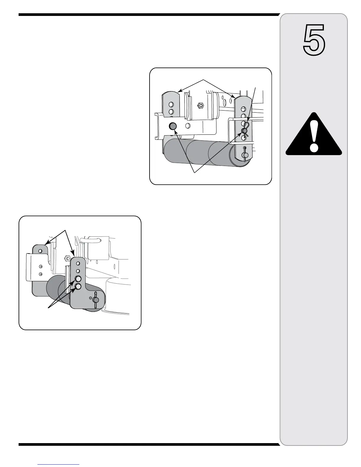
50" Deck ONLY
The 50" deck roller assembly index bracket has five
adjustment positions holes.
• While supporting the roller assembly, remove click pin
and withdraw the clevis pin from both the left and right
roller index brackets. See Figure 14.
• Position the roller assembly so that the rollers are ap-
proximately 1/4" to 1/2" above the flat surface below.
• Align the nearest index bracket holes with the holes
in the deck mounting brackets. Insert the clevis pins
through the deck brackets and the index brackets and
secure with the click pins. See Figure 14.
NOTE: The clevis pins should be in the corresponding
holes of both the left and right roller index brackets.
Figure 14
WARNING
Never attempt
to make any
adjustments while
the engine is
running, except
where specified
in the operator’s
manual. Stop the
engine before
performing any
adjustments.
Clevis Pin
Index Brkt.
Click Pin
 Loading...