22 se c t i O n 6— Ma i n t e n a n c e & ad j u s t M e n t s
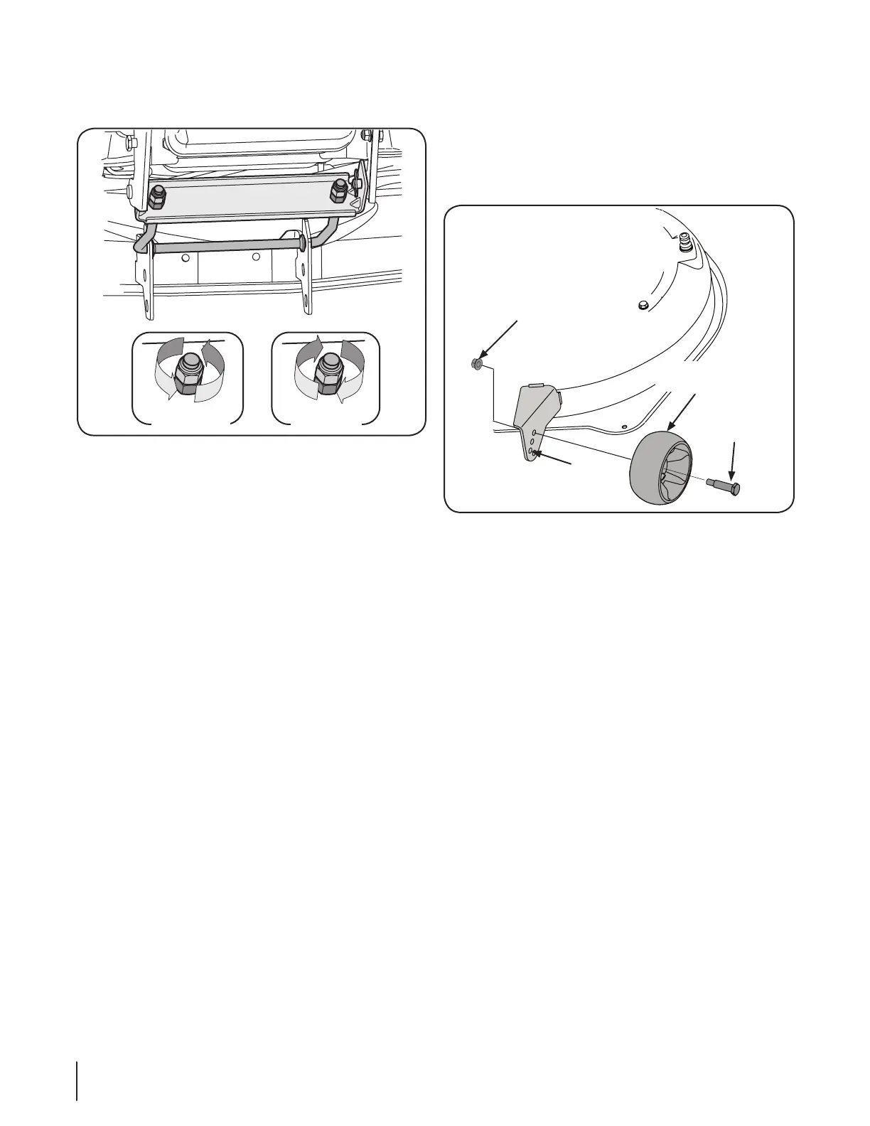
Working at the front of the tractor, loosen the two hex lock nuts 3.
at the front of the deck hanger rod. Thread the lock nuts
away from the hex nuts behind them. Refer to Fig. 6-6.
Use a open end wrench to turn the inner hex nuts to adjust the 4.
front of the deck. Turn the hex nuts clockwise to raise
the front of the deck, or counterclockwise to lower the
front of the deck. Adjust the hex nuts evenly so that the
deck hanger rod is at the front of both slots in the hanger
bracket on the front of the deck. See Fig. 6-6.
Retighten the two hex lock nuts when properly adjusted.5.
Deck Gauge Wheel Adjustment
NOTE: The deck gauge wheels are an anti-scalp feature of the
deck and are not designed to support the weight of the cutting
deck.
The deck gauge wheels should neither contact the ground, nor
be high off the ground, when the deck is moved to the desired
height setting. If you change your cutting height during the
mowing season, the gauge wheels should be checked and
adjusted as necessary. Adjust the gauge wheels as follows:
Place the tractor on a flat surface and move the deck to the 1.
desired mowing height using the deck lift lever.
Check gauge wheels distance from the flat surface below. If 2.
the gauge wheels contact the ground, they must be raised.
If the gauge wheels are higher than ⁄” above the ground,
they should be lowered.
Remove the flange lock nut and shoulder bolt securing one of 3.
the front ball wheels to the front index bracket. Reposition
the ball wheel to align with the one of five index holes that
places the wheel ⁄” to ⁄” above the ground. Secure the
ball wheel to the index bracket with the shoulder bolt and
flange lock nut. Note the index hole used and secure the
other ball wheel in the same position. See Fig. 6-7.
Lower Front
of Deck
Raise Front
of Deck
Figure 6-6
Flange
Lock
Nut
Shoulder
Bolt
Gauge Wheel
Bracket
Index Holes
Front Gauge
Wheel
Figure 6-7
 Loading...